Allowable Loads for Round Timber Poles
HCM-00752 View this publication in PDF form to print or download.
The following publication is a major upgrade of information for calculating and understanding the allowable loads for round timbers based on wood type. It includes the allowable load, allowable shear, allowable bending and modulus of elasticity for four different types of Alaska woods: birch, cottonwood, Alaska hemlock and Alaska spruce. Both Sitka spruce and white spruce are categorized as one spruce type.
What follows is a description of the basic analysis and parameters used in calculating uniform loads for round timbers.
Hulsey has provided an enormous service in this publication and we thank him both personally and professionally for an extensive effort benefiting all the shelter industry of Alaska and anyone who wants to build with our native woods.
— Richard D. Seifert
Introduction
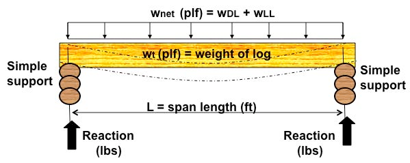
Beam span tables are provided for five species* of Alaska timber logs (poles): white spruce, Sitka spruce, Alaska hemlock, birch and cottonwood. The material properties for white spruce and Sitka spruce are treated the same; therefore, there are four tables (one for each species) that provide allowable uniform loads versus span and pole diameter. Each table includes spans from 6 feet to 33 feet and pole diameters of 6 inches to 24 inches. Because logs are normally tapered, the diameter listed in these tables is the smallest diameter found on the log. Uniform loads and support conditions are illustrated in Figure 1.
*National Grading Rules designations
Loads
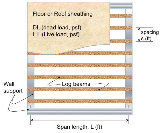
Each pole (log) beam is assumed to carry a uniform load that is composed of dead load, live load and weight of the log. Distributed live loads, LL, and superimposed dead loads, DL, apply pressure to an area of the roof or floor. These loads are in pounds per square foot (psf). Except for the weight of the log, the portion of load carried by each log consists of the uniform pressure times the beam spacing (s) or tributary width (feet) (see Figure 2). The result is a value (wnet) in pounds per linear foot (plf) that can be used in the design selection tables provided in this document.
Residential construction
Uniform dead load pressures are typically 15 psf for roofs and 10 psf for floors. You should verify these numbers for each application. Data on roof snow loads for each location in the state is available from the local building code or by contacting the local building department. If the log or pole is used as a roof beam, the amount of live load is the larger of either 20 psf or the code specified snow load. If your log is a floor beam, the live load is 40 psf for residential construction. The size of log needed to span the opening is different for each timber species, and log diameter and size is controlled by either strength or deflection. For example, the log may be strong enough but deflect too much or it may not deflect much but is not strong enough. The net uniform load to be carried by each log is given in Table 1.
Materials
Is a cottonwood log as strong as a white spruce log of the same diameter? This is answered by studying the material properties for each. The size of log depends on loading, span, spacing and species. Allowable stresses for each species are different (this affects strength) and modulus is also different for each species (this controls deflection). Table 2 provides the round timber strength and stiffness properties for five different Alaska species that may be used as pole (log) beams: white spruce, Sitka spruce, Alaska hemlock, birch and cottonwood.
The round timber strength and stiffness properties listed in Table 2 are based on small clear values as reported by the American Society for Testing and Materials (ASTM) in ASTM D2555 (white spruce, cottonwood and birch) or on the results of small clear testing conducted according to ASTM standards (Sitka spruce and Alaska hemlock). Allowable bending values were determined in accordance with ASTM D2899, section 16.1., allowable shear values were determined in accordance with ASTM D2899 section 17.1 and the modulus of elasticity was determined in accordance with ASTM D2899, section 18.1.
Beam strength and deflection comparisons
Beams carry load through shear and bending. Some species will carry more load than others. Table 3 provides a list of the best to the worst of the four species used in this document. Table 3 shows that in relation to cottonwood, birch is 144 percent stronger in shear, 174 percent stronger in bending and is stiffer, so for the same diameter and span, a birch log will deflect 65 percent better than a cottonwood log. If you compare Alaska hemlock with Alaska spruce, hemlock is stronger in bending, but spruce is better in shear and will not deflect as much (see the circled values).
| DL | LL | DL+LL | DL | LL | DL+LL | DL | LL | DL+LL | |
|---|---|---|---|---|---|---|---|---|---|
| 10 | 40 | 50 | 15 | 50 | 65 | 15 | 60 | 75 | |
| Spacing (s) | Superimposed Uniform Beam Loads (plf) | ||||||||
| (ft) | WDL | WLL | Wnet | WDL | WLL | Wnet | WDL | WLL | Wnet |
| 2 | 20 | 80 | 100 | 30 | 100 | 130 | 30 | 120 | 150 |
| 4 | 40 | 160 | 200 | 60 | 200 | 260 | 60 | 240 | 300 |
| 6 | 60 | 240 | 300 | 90 | 300 | 390 | 90 | 360 | 450 |
| 8 | 80 | 320 | 400 | 120 | 400 | 520 | 120 | 480 | 600 |
| 10 | 100 | 400 | 500 | 150 | 500 | 650 | 150 | 600 | 750 |
Note: Wnet = WDL+WLL. It excludes beam weight
| Species | Allowable Stresses Shear Fv (psi) | Allowable Stresses Bending, Fb (psi) | Modulus of Elasticity, E (psi) |
|---|---|---|---|
| Alaska Spruce (White & Sitka) | 164 | 1,285 | 1,180,000 |
| Alaska Hemlock | 145 | 1,589 | 1,130,000 |
| Birch | 191 | 2,021 | 1,590,000 |
| Cottonwood | 133 | 1,160 | 1,028,000 |
| Species | Shear Fv Coefficient Cv | Shear Fv % stronger | Bending, Fb Coefficient Cb | Bending, Fb % stronger | Modulus, E Coefficient Cb | Modulus, E % as flexible |
|---|---|---|---|---|---|---|
| Birch | 1.436 | 144 | 1.742 | 174 | 0.647 | 65 |
| Alaska Hemlock | 1.090 | 109 | 1.370 | 137 | 0.910 | 91 |
| Alaska Spruce (White & Sitka) | 1.233 | 123 | 1.108 | 111 0. | 871 | 87 |
| Cottonwood | 1.000 | 100 | 1.000 | 100 | 1.000 | 100 |
These species are compared to cottonwood.
Allowable Beam Selection Tables
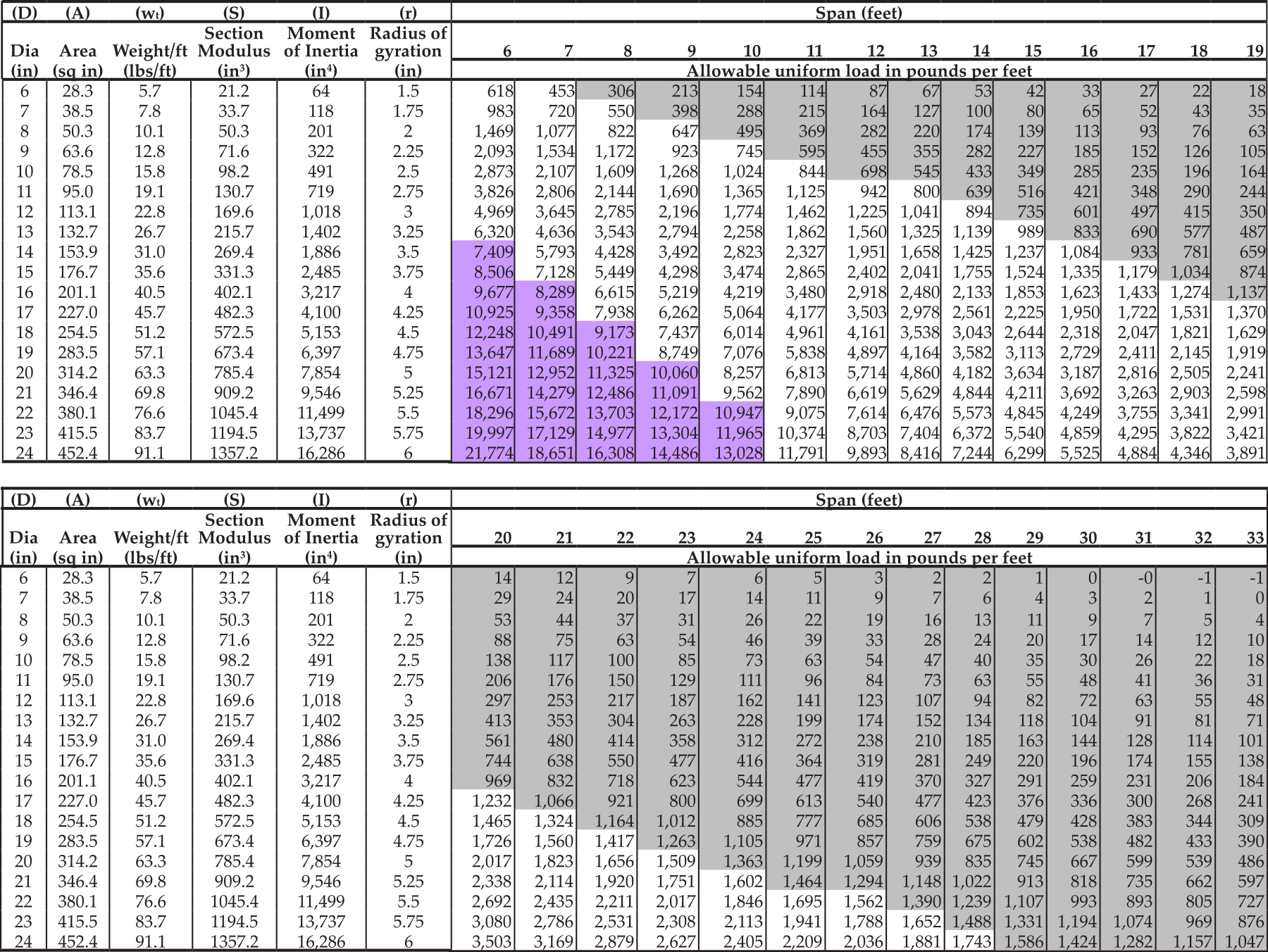
The design selection tables in this document provide allowable net load for simply supported poles (logs). Net load (plf) needed for these tables is the sum of the applied dead load and the applied live load (wnet = wDL+wLL). Tables for each timber species (Tables 4 to 7) include span lengths from 6 feet to 33 feet and log diameters from 6 inches to 24 inches. The net loads in these tables do not exceed allowable shear stresses or allowable bending stresses and are within a roof deflection limit of L/240.
Strength (allowable stress check)
Pole (log) beams carry a portion of floor load or roof load, and that value depends on the pressure loads to be carried and the beam spacing. Simply supported beams experience shear stresses and bending stresses. Typically, shear stresses are greatest near wall supports and bending stresses are greatest at midspan. Shear stresses and bending stresses are calculated by formula (see the technical section) for a uniform load (plf) that is supported by the beam that is to span an opening.
Beams are strong enough provided the calculated stresses are within the species-dependent allowable stresses. Shear stress will sometimes control where the span is short and the log diameter is large. Typically, bending stress controls for most spans. The allowable load selection tables provide pole (round log) diameters that are within both the allowable shear stress and allowable bending stress for each species.
Flexibility (limiting deflection check)
Once a beam is selected for strength it must be checked for deflection. Deflection is calculated by formula (see the technical section) using modulus of elasticity for the timber species. Net applied load (wDL+wLL) given in the allowable selection tables was checked for a roof span deflection limit of L/240. This is conservative, in that deflection limits typically apply to live load deflections.
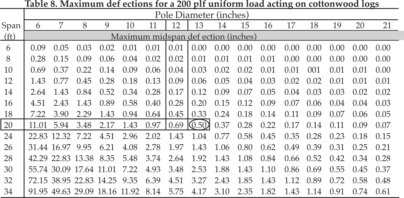
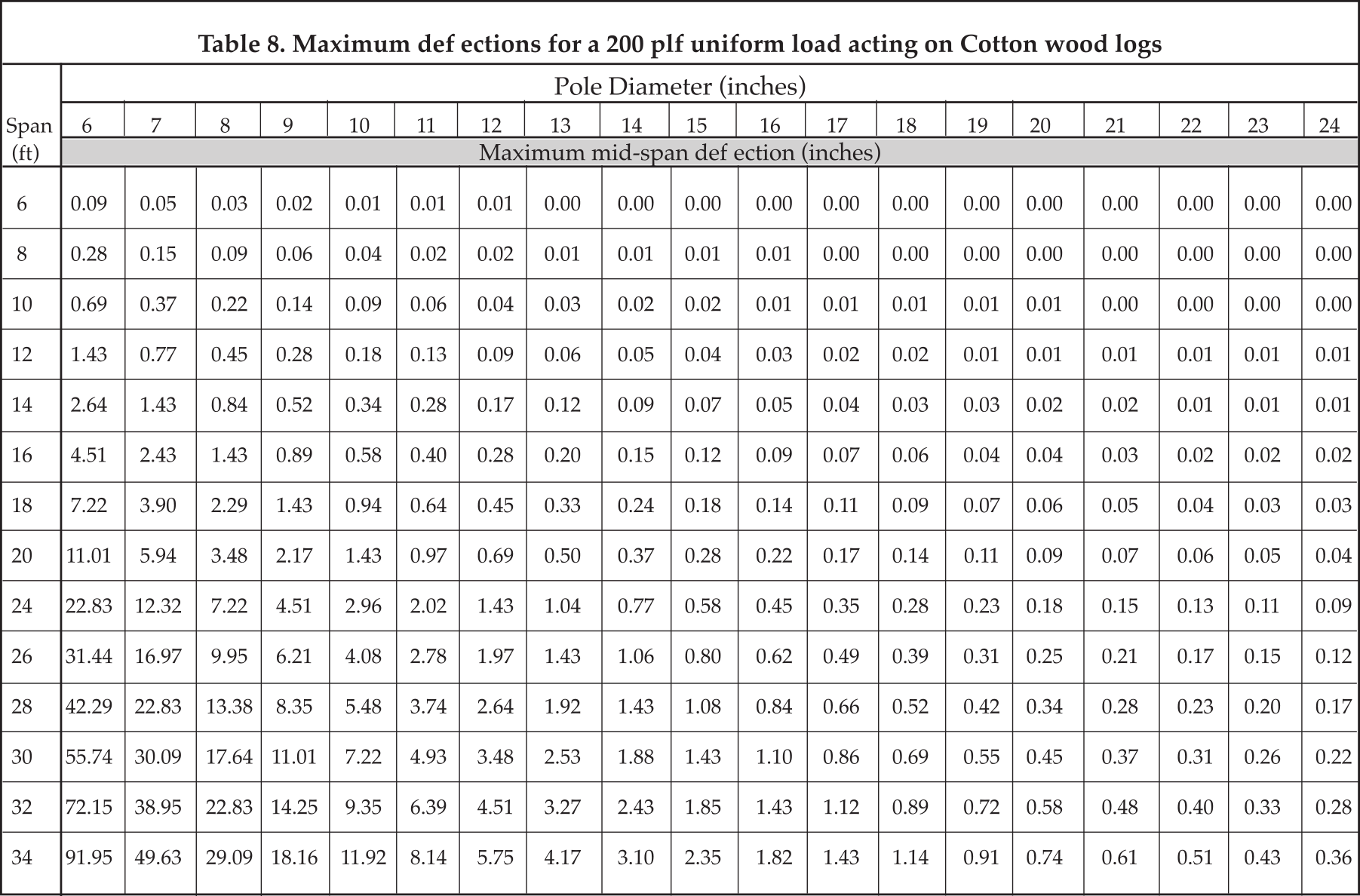
Calculated Deflections. Table 9 is provided to help evaluate alternative deflection limit choices. This table provides calculated beam deflections for a load of 200 plf acting on cottonwood with spans of 4 feet to 34 feet and log diameters of 6 inches to 24 inches. Information in Tables 1, 3 and 8 may be used to calculate midspan deflections for different loads and species.
∆ = CE (w/200plf )∆C
Where w is the uniform applied load (plf) on your beam. CE is a coefficient to correct the deflection to your species type (see Table 3). Deflection in Table 9 was calculated using cottonwood and a uniform load of 200 plf. This deflection is given in inches and may be described by (ΔC).
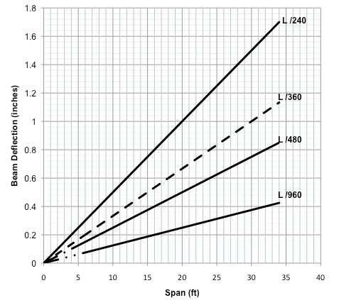
Deflection limits. If a beam is too flexible, brittle finishes such as plaster or gypsum board may crack and doors and windows may become inoperable. Therefore, we must keep the maximum expected live load deflection within an acceptable limit. The general rule of thumb is that beams supporting brittle finishes such as gypsum board or plaster should be limited to a live load deflection not to exceed the span length divided by 360. For members supporting less brittle finishes such as tongue- and-groove paneling, the deflection limit is relaxed to L/240. Added floor stiffness is now considered important to floor performance. For example, in 3-Star homes, the floor live load deflection limit is L/480 and in 4-Star homes, floor live load deflections are limited to L/960. These deflection limits are illustrated in Figure 3.
Beam Sizing Procedure
The following describes how beam selection information may be used for your application. In every case, you should seek the assistance of an engineer.
Step 1. Determine floor or roof dead load (DL) and the superimposed floor or roof live load (LL).
Step 2. Find the acting beam load (plf). Multiply log spacing by sum of (DL+LL) or use Table 1.
Step 3. Use the appropriate allowable selection table (Tables 4 to 7) and determine the allowable net uniform load for your span, log diameter and species. If the table value is equal to or larger than the acting load from step 2, your pole or log beam will be within the allowable shear and bending stresses (it is strong enough) and deflection for the net applied load will be within the limiting deflection of L/240.
Step 4. If you believe the deflection limit is sufficient, you are finished; otherwise use Table 9 and determine for your span and log diameter the midspan deflection for a cottonwood with a 200 plf acting load. The calculated deflection is to be corrected for the species and the applied load as discussed above. Now check the deflection versus the deflection limit. If it is within the limit, you are done. Otherwise, enlarge the diameter and repeat.
Examples
Example 1
Consider that we want to install a roof on a 20-foot- by-30-foot building near Fairbanks, Alaska. We want a roof that will carry the IBC 2006 snow loads with a L/480 live load deflection limit. We will use white spruce timber poles spaced at 4 feet on center to span the 20-foot width. The roof system dead load (DL), including insulation and lights, is assumed to be 15 psf. The roof live load (LL) is a 50 psf snow load.
Step 1. The loads acting on the roof are: DL = 15 psf, and LL = 50 psf; DL+LL = 65 psf
Step 2. Determine the amount of load that each log is to carry. Except for its own weight, the load carried by each log may be found from Table 1. It can be seen that for a DL of 15 psf, and a LL of 50 psf, with a spacing of 4 feet, the load that will be applied to the log is 260 plf (circled). The allowable uniform load must be equal or greater than the applied load.
Alternatively, the load carried by each log could have been calculated by multiplying log spacing and the pressure load to give
wD = 4(15 psf) = 60 plf
wLL = 4(50 psf) = 200 plf
wnet = wDL + wLL = 60 + 200 = 260 plf
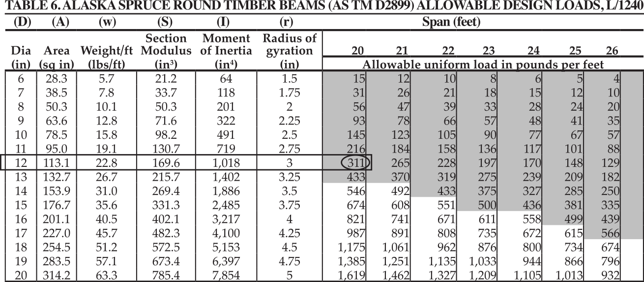
Step 3. Select the required log diameter. Use Selection Table 6 and select the 20-foot span vertical column until you find an allowable load that is equal to or larger than 260 plf. The result is a 12-inch diameter that is controlled by the deflection limit of L/240. The allowable uniform load for an Alaska spruce 12-inch diameter log with a 20-foot span is 311 plf. Values in light grey mean it is controlled by the L/240 deflection limit. An 11-inch log only carries 216 plf, which is less than the acting load and will not be sufficient.
| DL | LL | DL+LL | DL | LL | DL+LL | DL | LL | DL+LL | |
|---|---|---|---|---|---|---|---|---|---|
| 10 | 40 | 50 | 15 | 50 | 65 | 15 | 60 | 75 | |
| Spacing (s) | Superimposed Uniform Beam Loads (plf) | ||||||||
| (ft) | WDL | WLL | Wnet | WDL | WLL | Wnet | WDL | WLL | Wnet |
| 2 | 20 | 80 | 100 | 30 | 100 | 130 | 30 | 120 | 150 |
| 4 | 40 | 160 | 200 | 60 | 200 | 260 | 60 | 240 | 300 |
| 6 | 60 | 240 | 300 | 90 | 300 | 390 | 90 | 360 | 450 |
| 8 | 80 | 320 | 400 | 120 | 400 | 520 | 120 | 480 | 600 |
| 10 | 100 | 400 | 500 | 150 | 500 | 650 | 150 | 600 | 750 |
Step 4. Stiffen roof beams so the live load deflection is within the L/480 limit. The roof live load from Step 2 is wLL = 200 plf. The midspan live load deflection is determined from Tables 3 and 8. In Table 8 the load is 200 plf. Enter with a 20-foot span and a 12-inch diameter log. The deflection for this cottonwood log is 0.69 inches. Spruce is 87 percent as flexible as cottonwood (see Table 3). Therefore, the midspan deflection is
∆ = (0.871)(0.69 inches) = 0.6 inches
The deflection limit from Figure 3 is 0.5 inches. Therefore, increase the diameter to 13 inches. Now, check the answer. A 13-inch cottonwood log deflects 0.5 inches (see Table 8). White spruce will deflect 87 percent of this value or 0.44 inches.
Alternatively, the deflection could be checked by formula (see the technical section for details). Modulus of elasticity for white spruce is given in Table 1 of the text and is E =1,180,000 psi. The moment of inertia for a 12-inch diameter log is given in Design Tables 4 – 7 and is I = 1,018 in4. Use the uniformly loaded simple beam deflection equation to check if this will be satisfactory (see the technical section).
| Species | Shear Fv Coefficient Cv | Shear Fv % stronger | Bending, Fb Coefficient Cb | Bending, Fb % stronger | Modulus, E Coefficient Cb | Modulus, E % as flexible |
|---|---|---|---|---|---|---|
| Birch | 1.436 | 144 | 1.742 | 174 | 0.647 | 65 |
| Alaska Hemlock | 1.090 | 109 | 1.370 | 137 | 0.910 | 91 |
| Alaska Spruce (White & Sitka) | 1.233 | 123 | 1.108 | 111 0. | 871 | 87 |
| Cottonwood | 1.000 | 100 | 1.000 | 100 | 1.000 | 100 |
∆max = 5wLL L(12L)3 / 384EI = 5(200)(20)(12 x 20)3 / 384(1,180,000)(1,018) = 0.599 in.
The allowable deflection is given by
∆(limit) = 12L / 480 inches = 12(20f) / 480 = 0.5 inches
The calculated deflection at midspan exceeds 0.5 inches; therefore, we need to increase pole diameter to 13 inches. The moment of inertia for a 13-inch diameter log is I=1,402. This gives
∆max = 0.599 ( 1,018 / 1,402 ) = 0.44 inches
This calculated maximum deflection of 0.44 inches is below the 0.5-inch deflection limit. Thus, we may use 13-inch diameter logs spaced at 4 feet on center for a roof span of 20 feet.
Structural Engineering Concepts and Commentary (technical section)
Mechanical Sectional Properties for Round Beams
A pole or log's sectional properties are dependent upon the diameter (D). Calculations and tabulated data found in this document are based on minimum diameter or diameter at the top of the log. Mechanical (geometric) sectional properties needed to design a round timber beam (pole or log) are area (A), moment of inertia (I) and section modulus (S). The cross sectional area (A) for a round timber pole is given by the following equation:
A = πD2 / 4
D is the minimum diameter of the pole, or the diameter at the top, and π = 3.14. Moment of inertia (I) is used to determine stiffness of the pole. This property is given by the following equation:
I = πD4 / 64
Section modulus (S) is used to determine a log's ability to resist bending. This property is given by the following equation:
S = πD3 / 32
Structural Considerations
Design tables in this document were developed using an Allowable Stress Design (ASD) approach. Consider a simply supported uniformly loaded beam. Once loaded, it experiences shear stresses, bending stresses and deflects (see Figure 4). Since beams must be both strong enough and stiff enough, the design process consists of two parts. First, we must check to ensure that both shear stresses and bending stresses do not exceed the allowable stresses for the selected timber species. Second, once a beam has been selected that is strong enough, the midspan deflection must be calculated for the selected timber species. This deflection must be within allowable deflection limits.
Strength. Shear attempts to distort the cross section, which causes stress in the timber section. Moment causes the beam top to shorten and the beam bottom to lengthen. These length changes cause internal bending-type stresses. Typically, shear is greatest at end supports and moment and deflection is greatest at midspan. The maximum shear stresses (near end supports) are calculated and compared with the timber species allowable shear stresses. The maximum bending stresses (midspan) are calculated and compared to the timber species allowable bending stresses. The calculated shear stresses and calculated bending stresses shall not exceed the allowable stresses for the timber species given in Table 2.
Stiffness. The beam may be sufficiently strong but too flexible. For example, in a floor, excessive movement may occur as people wall across the floor. If a beam supports a ceiling or is used to frame over a door or window opening, excessive deflections may cause brittle finishes to crack or cause doors and windows to bind or become inoperable. Therefore, maximum midspan deflections are calculated and compared to building code recommended allowable limits.
Loads, Stresses and Deflections
Loads. Typically, log beams support uniform loads such as those illustrated in Figures 1, 2 and 4. The total uniform load (w) is composed of beam self weight (wt), superimposed dead loads (wDL) and non-permanent loads such as snow and people (live load, wLL). These loads are expressed in pounds per linear foot (plf).
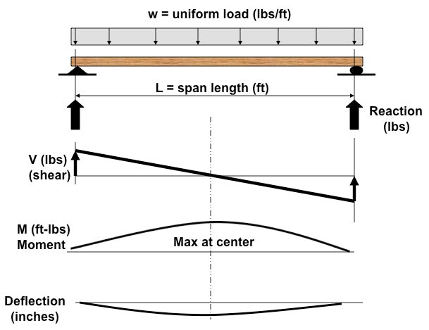
Distributed live loads (LL) and superimposed dead loads (DL) apply pressure to an area (see Figure 2). These loads are expressed in pounds per square foot (psf). Uniform loads acting on the beams are a combination of beam self weight and the super- imposed loads. The load carried by each beam is determined by multiplying pressure loads (psf) by the beam spacing (s) or tributary width (feet). The result is a value in pounds per linear foot (plf) that can be used in the following tables to determine the minimum diameter required for a particular beam span and species. Typically, uniform dead load pressures are approximately 15 psf for roofs and 10 psf for floors. However, designers should verify these numbers for their own particular application. Code requires a floor live load of 40 psf for residential construction. Roof snow loads can be determined for various locations in the state by contacting the local building department, reviewing the current edition of ASCE-7, Minimum Design Loads for Buildings and Other Structures, or studying the current edition of the building code that has been adopted for your region. The total uniform load is given by the following equation:
w = wt + wDL + wLL
w = wt + wnet
where
w = Total uniform load, plf;
wt = Beam self weight, plf;
wDL = Superimposed dead load, plf;
wLL = People or snow loads, plf; and
wnet = wDL + wLL = Combination of superimposed dead load and live loads.
The beam self weight is found by this equation:
wt = γA / 144
Timber density, γ(pcf)), is multiplied by the cross- sectional area of the pole, A (square inches). Uniform superimposed dead and live loads are obtained by these formulas:
wDL = DL x s
wLL = LL x s
Uniform dead load (wDL) carried by the beam, is found by multiplying floor or roof pressure, DL (psf), by beam spacing, s (feet). The uniform beam live load, wLL, is found by multiplying floor or roof live load pressure, LL (psf), by beam spacing, s (feet) (see Figure 2).
Reactions. Reactions are needed to size columns, hanger brackets and other structural elements that support the beam ends. Reactions for a simply supported uniformly loaded log beam can be determined with the following equation:
R = wL / 2
L is span length (feet), w is uniform load in pounds per linear foot (plf) and R is the end of beam reactions expressed in pounds.
Shear Stress. The cross sections of all loaded beams resist shear. Shear stress usually governs short beams: however, shear stresses for all spans must be checked and compared to the allowable values presented in Table 2. Shear stresses can be approximated with sufficient accuracy by the following equation:
fv = V / A ≤ Fv
Here, fv (psi) is the calculated shear stress, Fv (psi) is the allowable shear stress from Table 2, A is the member cross-sectional area (square inches) of the member and V (pounds) is the shear which is conservatively equal to the reaction determined above (see Figures 2 and 4). Note that shear stresses are typically greatest at supports or locations where concentrated loads are applied.
Flexure or bending stress. When a beam is subjected to a transverse load, it deflects. As a beam deflects, the top of the beam shortens (compression) and the bottom stretches (tension); this is known as bending. The extreme upper and lower surfaces of the member are where the compression and tension stresses in the beam are greatest. In order to prevent a flexural failure of a beam, bending stresses must be checked and compared with the allowable values in Table 2. One way to determine the bending stress in a member is to first determine the maximum bending moment (see Figure 4). For a simply supported beam, this moment is in the middle of the span and is obtained by using the following equation:
M = wL2 / 8 (ft - lbs)
Here, w (plf) is the total uniform load, L (feet) is the span and M (foot-pound) is the maximum moment (located at midspan). This maximum bending moment is then used to calculate the expected maximum bending stress which is obtained by using the following equation:
fb = M / S ≤ Fb = [ 12wL2 / 8 ] ≤ Fb
M (foot-pound) is the bending moment, S expressed in cubic inches is the section modulus given in the tables at the end of this document, fb (psi) is the calculated bending stress and Fb (psi) is the allowable bending stress from Table 1. Please note that the above equation converted the bending moment units from foot-pounds to inch-pounds, so no additional unit conversion is necessary. As can be seen from the bending moment diagram in Figure 4, moment in simply supported beams varies from zero at the ends to maximum at the midspan. It is the midspan moment that we must account for.
Deflection. There are two different properties that control the size of a structural beam member: one is strength and the other is deflection (serviceability). Strength is checked by selecting size so that the actual shear stresses and the actual bending stresses do not exceed the tabulated allowable stresses given in Table 2.
Serviceability, on the other hand, is based on limiting deflection to maintain the functionality of building elements such as doors, windows and finishes. Consider a beam that meets the allowable shear and bending stress criteria but exceeds the maximum defection limits. Brittle finishes such as gypsum board and plaster may crack and doors and windows may become inoperable. Therefore, it is important to keep deflection within acceptable limits based on building code requirements.
∆max = 5wLL L(12L)3 / 384EI ≤ ∆allowable
Δmax = Maximum live load midspan deflection (inches);
Δallowable = Limiting live load midspan deflection (inches);
wLL = Uniform live load acting on the beam (plf);
L = Span length (feet);
E = Modulus of the timber species (psi), see Table 2; and
I = Moment of inertia (inches4), see Tables 4 to 7. Cross section values are provided for pole diameters.
The general rule of thumb is that structural elements supporting brittle finishes such as gypsum board or plaster be limited to a deflection not to exceed the span length of the beam divided by 360. This is expressed by ∆allowable = L/360 where ∆allowable is the maximum deflection and L is the span length in inches. For members supporting less brittle finishes such as tongue and groove paneling, deflection limits are relaxed to ∆allowable = L/240. These deflection limits are considered minimal requirements. If you want a stiffer roof or floor, you can limit the deflections to smaller deflections such as L/480 or L/960.
Development of the Allowable Load Tables
The allowable load tables provided in this document are based on applying a uniform load to simply supported beams with round timber cross sections. The ASD method was used to find an allowable load that would not exceed an allowable shear stress or an allowable bending stress. The tables provide for Alaska white spruce, Sitka spruce, Alaska hemlock, birch and cottonwood.
In the ASD method, when a beam size is controlled by strength, the member selected does not exceed allowable stress levels for shear or for bending. Typically, short spans are controlled by shear and long spans are controlled by bending. The tabulated uniform loads, in pounds per foot, are given based on the controlling values of shear and flexure and checked for a deflection limit for roofs of ∆allowable = L/240. Allowable loads were calculated for shear, bending and the deflection limit of L/240. The lesser uniform load of these three is shown in the table. The condition that led to the least allowable uniform load (plf) is shown by color. Once you find the net available uniform load, the available uniform live load is:
wLL = wnet - wDL
Here, wLL is the allowable uniform live load (plf), wnet is the allowable uniform load (plf) that can be carried by the log beam and wDL is the superimposed dead load in addition to the log self weight (plf) that is acting on the log beam. Remember that wDL is typically determined using tributary width (beam spacing) times the weight of the structural framing that is to be carried by the beam. This is:
wDL = 15s; (residential roofs)
= 10s; (residential floors)
Here, s (feet) is beam spacing or tributary width (feet) that is carried by the beam. The allowable load that can be carried by any given pole (log) beam was calculated to meet both strength and serviceability criteria. The strength criteria means the section will be within allowable shear and allowable flexure stresses. Allowable deflection limits depend on the type of application.
Shear. Allowable loads were calculated to not exceed the allowable shear stress, Fv (psi), for the timber species (see Table 1). This was done by:
wnet = ( 2FvA / L ) - wt
Here, wnet is the allowable uniform design load (plf) that can be applied to the round timber pole, which is given by this formula:
wnet = wDL + wLL
wDL = Dead load supporting structure excluding pole weight in pounds per linear foot (plf) wLL = Allowable uniform live load that can be applied to the round timber pole in pounds per linear foot (plf)
wt = Self weight of the log in pounds per linear foot (plf)
A = Cross-sectional area of the round pole in square inches
L = Span of the pole in feet
Flexure. Allowable loads were calculated to not exceed the allowable bending stress, Fb (psi) for the timber species (see Table 1). This was done by this equation:
wnet = ( 8FbS / 12L2 ) - wt
Again, wnet is the allowable uniform design load (plf) that can be applied to the round timber pole and, as for shear, is given by this formula:
wnet = wDL + wLL
wDL = Dead load supporting structure excluding pole weight in pounds per linear foot (plf) wLL = Allowable uniform live load that can be applied to the round timber pole in pounds per linear foot (plf)
wt = Self weight of the log in pounds per linear foot (plf)
A = Cross-sectional area of the round pole (square inches)
L = Span of the pole (feet)
S = Section modulus (cubic inches)
Deflection. The following tables were prepared for structural members associated with roof framing where the allowable deflection is limited to L/240. If the allowable load based on deflection is smaller than either the value for shear strength or the value for bending strength, the table will provide the allowable based on the deflection. The allowable uniform load based on the deflection limit is given by:
wnet = ( 384 / 5 )( EI / 144L4 )(∆allowable) - wt
Again, wnet is the allowable uniform design load (plf) that can be applied to the round timber pole and is given by this equation:
wnet = wDL + wLL
wDL = Dead load supporting structure excluding pole weight in pounds per linear foot (plf);
wLL = Allowable uniform live load that can be applied to a round timber pole in pounds per linear foot (plf)
wt = Self weight of the log in pounds per linear foot (plf)
E = Modus of elasticity (psi)
I = Moment of inertia (in4)
L = Span of the pole (feet)
∆allowable = L/240 = The allowable roof beam deflection limit (feet)
The allowable deflection for roof beams when corrected to units of inches is given by:
∆allowable = 12L / 240
Note: the allowable loads for deflection were calculated to be keep net weight within the deflection limits. This is conservative in that the net weight includes some dead load of the superimposed structure. If you want to determine allowable live load (plf) for more restrictive deflection limits, use the following equation:
wnet = ( 384 / 5 )( EI / 144L4 )(∆allowable) - wt wLL = Allowable uniform live load that can be applied to a round timber pole in pounds per linear foot (plf)
wt = Self weight of the log in pounds per linear foot (plf)
E = Modus of elasticity (psi)
I = Moment of inertia (inches4)
L = Span of the pole(feet)
∆allowable = Allowable roof beam deflection limit (feet)
If the pole (log) beam is to be used to support brittle finishes such as gypsum board, plaster or tile, the maximum allowable live load deflection prescribed by code is ∆allowable = L/360. So, to check your beam using the tables for your span and allowable uniform load, select your size and use the above equation with the more restrictive deflection. If you wish to use the 3-Star or 4-Star requirements, use L/480 or L/960 for the allowable deflection in the above equation.
Use of the Allowable Load Tables
Allowable design loads (plf) are provided for simply supported roof timber pole roof beams. The tables provide for 6-inch to 24-inch diameter poles and span lengths from 6 feet to 33 feet. Allowable loads were calculated for white spruce, Sitka spruce, Alaska hemlock, birch and cottonwood.
Member sizes were selected by the allowable stress design method (ASD) and checked for deflections so that it the beam did not exceed L/240. The table provides the user with a net allowable load in pounds per linear foot (plf) which is:
wnet = wDL + wLL
If you wish to determine if your member will carry the acting live load, use the table allowable net uniform load and deduct the acting superimposed dead load that is being carried by the beam. The resulting allowable live load in pounds per linear foot (plf) will be:
wLL = wnet - wDL
wnet is the allowable uniform load provided by the table and wDL is the dead load (excluding beam weight, wt) carried by the beam. If you wish to make the deflection limit more restrictive, you may check the acting uniform live load, wLL, in pounds per linear foot (plf) so as to not exceed your deflection limit such as ∆allowable = L/480. This is done as follows:
∆max = 5wLL (12L)2(L)2 / 384EI ≤ ∆allowable (ft)
wLL = Acting uniform live load that can be applied to a round timber pole in pounds per linear foot (plf);
E = Modus of elasticity (psi)
I = Moment of inertia (inches4)
L = Span of the pole (feet)
∆max = Calculated live load deflection
References
American Society for Testing and Materials (ASTM). 2003. Annual Book of ASTM Standards 2003, Section 4: Construction, Volume 04.10: Wood. ASTM, West Conshohocken, Pennsylvania. Referenced Standards: D2899-03, D2555-98.
Forest Products Lab, USDA 1963. Characteristics of Alaska Woods. FPL-RP-1, USDA Forest Serv., Forest Prod. Lab., Madison, Wisconsin.
Warning
Be sure to consult the current local building code and the appropriate building department that is responsible for buildings erected in your location. If your situation is other than simply supported (more than two supports), you should seek assistance from an engineer. For this condition, shears, moment and deflections are different than discussed in this document. We recommend before construction that you have your design reviewed by a professional engineer.
BUILDING IN ALASKA
TABLE 4: ALASKA BIRCH ROUND TIMBER BEAMS (ASTM D2899) ALLOWABLE DESIGN LOADS, L240 DEFLECTION
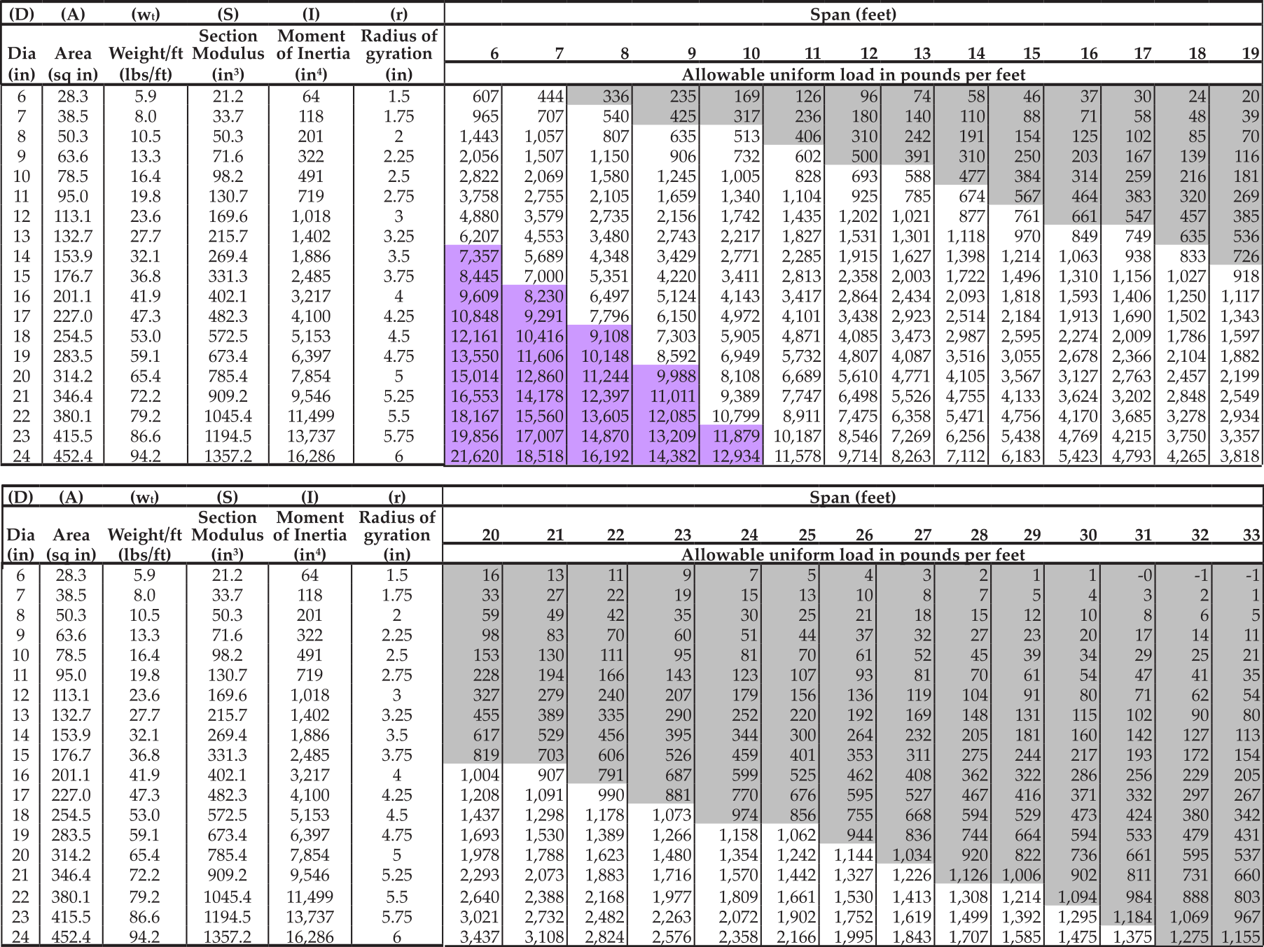
TABLE 5: ALASKA COTTONWOOD ROUND TIMBER BEAMS (ASTM D2899) ALLOWABLE DESIGN LOADS, L240 DEFLECTION

TABLE 6: ALASKA SPRUCE ROUND TIMBER BEAMS (ASTM D2899) ALLOWABLE DESIGN LOADS, L240 DEFLECTION
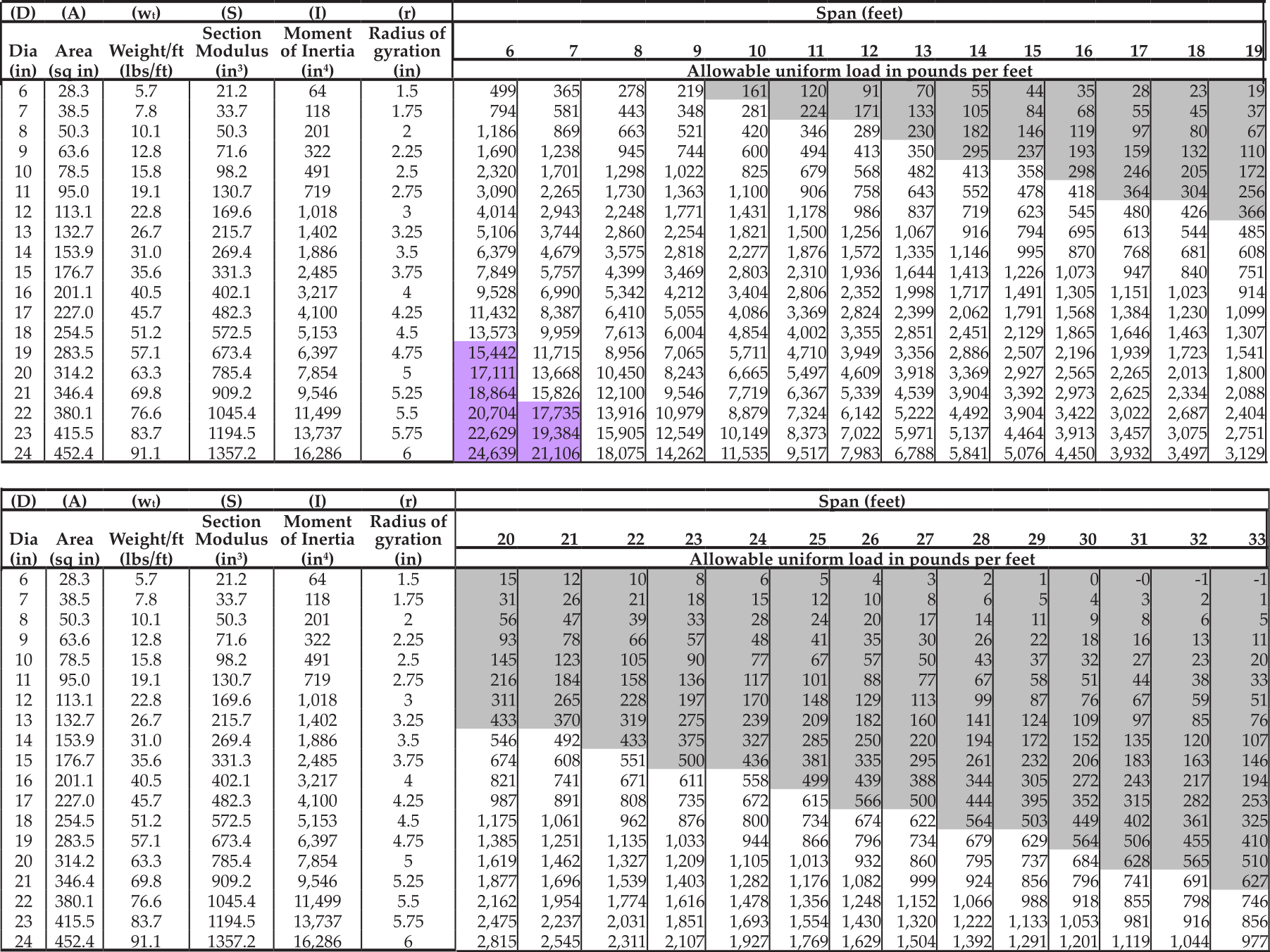
TABLE 7: ALASKA HEMLOCK ROUND TIMBER BEAMS (ASTM D2899) ALLOWABLE DESIGN LOADS, L240 DEFLECTION
The tables in this publication are calculated specifically for Alaska wood species. Wood properties can exhibit significant variation. It is suggested that when using these tables, the user engage the services of a professional engineer.
The University of Alaska Fairbanks Cooperative Extension Service cannot be held liable for any misuse or failure of beams used with this information.
Art Nash, Extension Energy Specialist. Originally written by Axel R. Carlson, former Extension Engineer and revised by J. Leroy Hulsey and John Bannister, Department of Civil and Environmental Engineering, University of Alaska Fairbanks.
Reviewed March 2022
