Foundation Retrofit and Rehabilitation
HCM-01555 View this publication in PDF form to print or download.
Introduction
This publication has been translated from Norwegian. It is taken from a series of publications produced by the Norwegian Building Research Institute (NBI) series, “Byggdetaljer,” which literally translated means “building details.” It is hoped that Alaskan builders will be able to glean useful ideas from this publication. The translations were done by Dr. Nils Johanson and Richard D. Seifert of the University of Alaska Fairbanks with the cooperation and permission of NBI, Oslo, Norway. The financial support for the translations and printing came through the Alaska Department of Community and Regional Affairs, from USDOE Grant DE-FG06-80CS6908.
0 GENERAL
- This bulletin gives an overview of the various methods that can be utilized to improve older building foundations and to retrofit building foundations. It also gives information about common damage to foundations and basement walls.
- The condition of the foundation can be a determining factor as to whether a building can or should be improved. Extensive repair or retrofitting are quite expensive to carry out and must be carefully evaluated ahead of time. A certain amount of tilt and some cracks in old buildings is acceptable if settlement has stopped. All large scale retrofit work demands professional assistance in evaluating the geotechnical and structural conditions.
- A technical survey combined with a historical survey of the foundation and foundation walls should be carried out in connection with improvements. The extent of the analysis depends on the size of the building, its age, foundation conditions, changes in use, and so on. The analysis may include the following:
- Investigation of construction records and government archives to map the soil conditions
- Survey of foundations and foundation walls
- Report of damage
- Visual survey and ground excavations
- Crack survey
- Foundation survey including drilling, testing etc.
- Report of settlements and time dependent settlements (precision leveling, precision settlement measurements)
- Calculation of the foundation load (static system)
- Measurements of groundwater level and pore water pressure
- Leveling and straightening of foundation and other walls
- Stress measurements in existing tension ribbons
- Vibration measurements
- Control of material quality
- Changes and improvements in the building foundation can lead to great problems with adjacent structures. For instance, buildings that are still settling may “hang up” on the area that has been improved. Strengthening or retrofitting must, therefore, take neighboring structures into account.
- Rehabilitating the foundation may also require correcting already existing differential settlement. Such correction is often possible by jacking wooden frame houses. Masonry construction is often sensitive to movement and should not be jacked or leveled.
1 TYPES OF FOUNDATION DAMAGE
11 Erosion
111 Natural rock
The durability and strength of rock is determined by the amount and distribution of the smallest and weakest mineral. As these minerals are worn away everything breaks down or dissolves, and there are no connections left between the other stronger mineral groups. The original stone then consists of a conglomeration of loose particles. If the foundation surface has been damaged by frost action, salt washing or the like, the deterioration accelerates. It usually takes a long time before natural rock starts to erode, but limestone, sandstone, and shale are more likely to be exposed to problem-causing erosion.
112 Brick
Brick is the most porous foundation material and will absorb moisture. The moisture leads to frost damage which materializes by exfoliation or splitting of the surface parallel to the outside. Large continuous cracks can totally destroy the bricks. The brick’s frost resistance depends on material properties such as pore distribution, water absorption, and strength. Other factors such as moisture, climate, number of freeze-thaw cycles, and the freezing speed are also important.
12 Rot
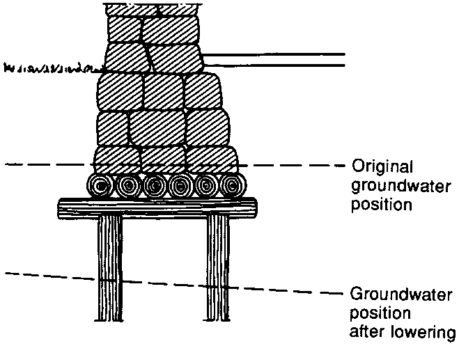
Fungus rot is the most common reason for damage to wood. Fungus thrives on nutrients that are found in wood. However, the temperature must be between 0 and 40°C and the wood must have at least 20% water with respect to its dry weight in order for the fungus to grow. Another important element in fungus rot in wood foundations is the availability of oxygen.
Raft and pile foundations are subjected to attack by fungus rot when the water table sinks below the top of the foundations (see Figure 12; see also Point 151.)
13 Insects
Insects can attack wooden foundations above ground level. Boring beetles and carpenter ants are the wood boring insects that do the most damage. Certain parts of the country are more exposed to attacks than other parts. Most wood-boring insects are active between 0 and plus 30°C (32°F and 85°F). Wood that has already been damaged by rot is especially vulnerable to attack by wood boring insects. The same conditions are true for caissons and poles at beaches.
14 Moisture damage
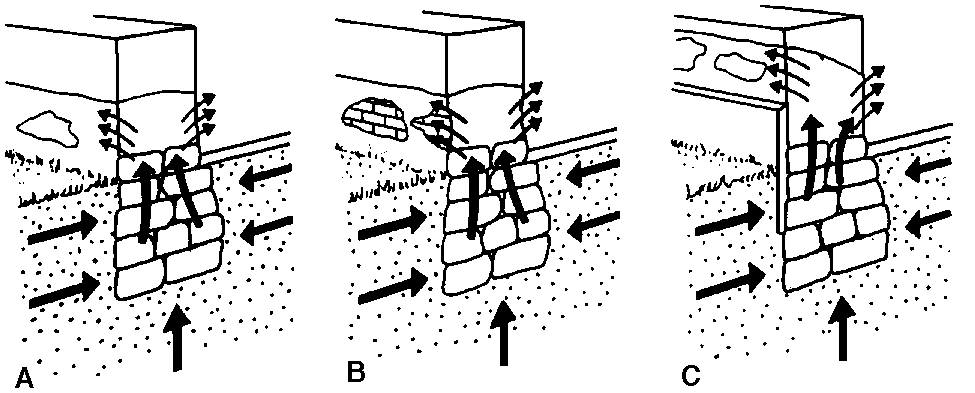
Walls where lime and clay are used as a mortar often absorb moisture. This usually does not lead to significant problems as long as the wall has been untreated or has been covered with lime mortar. Local repairs with cement mortar on an original lime mortared foundation wall does not work very well. The cement mortar, which is relatively tight, disturbs the moisture balance in the wall, and the mortar does not breath enough, nor does air escape. Moisture can thus penetrate farther up into the wall before it finds an exit (see Figures 14a to c). Old buildings are often surrounded by terrain which, because of occasional filling, asphalt work, and so on, lies higher than the original terrain. Mortar, masonry work, and possible wood construction, which were never designed to be in contact with the soil, can in this way suffer from significant moisture damage.
141 Frost wedging
Water that penetrates up or out through the wall can freeze and break it in pieces; the mortar material crumbles and loses its binding ability. In box walls the core can be torn to pieces, leaving the shell standing without any significant mortar.
142 Salt bloom
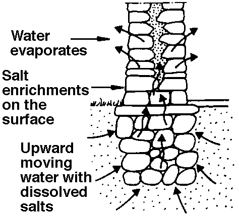
Moisture that travels in foundation walls can carry with it easily soluble salts that occur in mortar and stone material. These materials are carried to the outer surface where the water evaporates and the salt crystallizes. This "salt bloom" can damage the surface. Crystallization may also occur inside the rock or the cover and lead to of salt build-up, which can then flake off the covering mortar or rock material (see Figure 142).
15 Settlement
151 Groundwater lowering
The main reason for settling in Norwegian buildings is the lowering of groundwater. Settling occurs as a result of increased stress on the soil which causes compression of compressible soils. Raft foundations and the upper portion of wooden piles rot when the groundwater level sinks.
Changes in groundwater level or pore water pressure in the ground can be the result of one or more conditions.
- In Norway, ice static rebound following the last ice age that is still going on
- There have been many instances of groundwater table depression because of dewatering, especially in cities. Ditches and pipes that are placed below the groundwater level have contributed to its lowering. Construction of new buildings with deep foundations and basements has caused further drainage of the ground, as has tunneling through open loose rock. Local groundwater storage may also be disturbed by the removal of foundation sills.
- In towns and other built-up areas more and more of the terrain surface has been used for construction or covered with asphalt roads and parking places. In addition, there has been effective removal of the surface water via the drain system. A much smaller portion of natural precipitation reaches the ground and this contributes to a lowering of the groundwater level.
- Deciduous trees with large root systems have great demand for water. In certain cases they pull so much water from the ground that local groundwater levels are lowered and settling problems can occur.
152 Ground with limited bearing capacity
Some older building foundations are built without any concern for the bearing capacity of the underlying soil. Even in the construction phase, the building can start to settle. In extreme cases the foundation or the foundation wall will crack.
153 Uneven bedrock depth
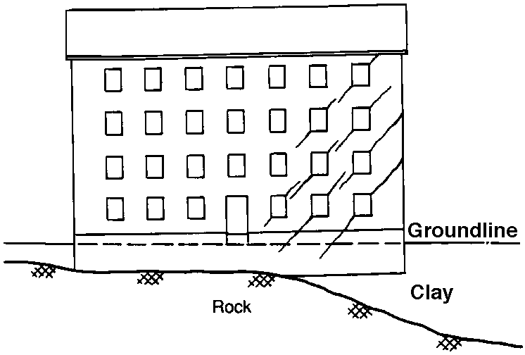
When a building is constructed partially on bedrock and partially on fill mass with poor bearing capacity, differential settling results. In masonry walls, such settling can have major consequences. Cracks can spread up through the various floors and, as a worst case, affect the stability of the entire building.
154 Excavations under foundations and poor backfill
With high loads and unfavorable ground conditions just excavating down to foundation level can cause settling. See Figure 154.
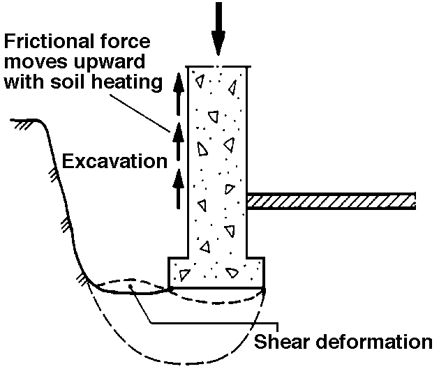
155 Increased Load
Buildings which have stood without damage for many years can experience settling if the load conditions are changed. Changes in use are often the reason for differential settlements and other damage to the foundation.
156 Removing neighboring houses
In cities where large buildings are close together, tearing down one structure can result in the neighboring building being left standing without lateral support. A slide, may then occur, and it can have serious consequences for the stability of the building.
16 Horizontal movement in the ground
In inclined terrain, by filling in of terrain, damage in the form of collapse of the foundation and basement walls because of increased earth pressure or poor stability can occur. In some cases, movement can also be caused by frost action, temperature variations or moisture variations.
17 Frost heave/adfreezing
Small older houses are usually not founded to frost-free depth if they do not have a basement. On frost-susceptible soil the damage to small house foundations can be extensive because of the adfreezing or the lateral grip of the frozen soil. The damage is normally more significant on walls where there is mortar between the blocks. Surface damage can also occur where there are connections with log houses (see Figure 17).
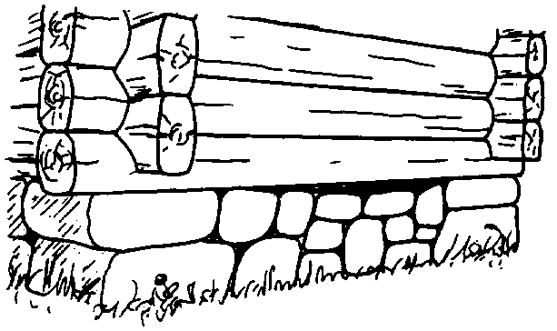
18 Alum Shale
Alum shale contains pyrite, which when exposed to oxygen (for instance by a lowered groundwater table) will be converted to sulfuric acid. This acid attacks concrete and metal. Sulfuric acid and lime form plaster of gypsum. When this process takes place there is a volume expansion which, in the worse case, can lift the foundation. Foundation damage in connection with alum shale is first and foremost related to the Oslo area. (Editor’s note: There is no known alum shale in Alaskan communities.)
2 IMPROVEMENT METHODS
21 Preventing Moisture Damage
211 Coating of the foundation wall. This method, which is little used in Norway, consists of establishing a capillary barrier in the foundation by drilling and injecting a mixture of polyester and rock flour.
212 Electro-osmosis
Electro-osmosis can also be used to prevent capillary absorption of water in masonry work. Electrodes are placed in the incision zone between the foundation wall and the soil. By changing the electrostatic conditions, the capillary rise can be reduced.
213 Drainage and irrigation
In some circumstances drainage and irrigation of the foundation can yield good results by reducing the moisture availability.
Draining and securing from moisture damage on the outside of basement wall is carried out after excavation.
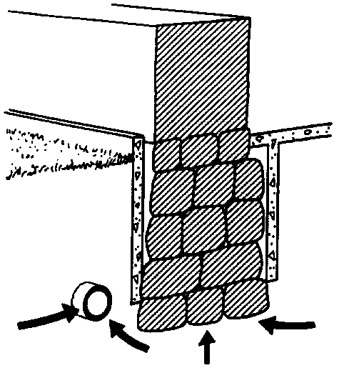
214 Sealing joints with lime mortar
This does not prevent air from entering the masonry work but it can reduce the extent of damage when the wrong kind of mortar has been used for improvements. Pure lime mortar is porous, and moisture which has been added can evaporate. Loose or poor-quality mortar should be chipped away and the cracks cleaned of dust and leftover mortar pieces. The cracks should then be moistened and filled with a lime mortar as similar as possible to the original mortar. The foundation wall should not be exposed to sun or rain during the curing time.
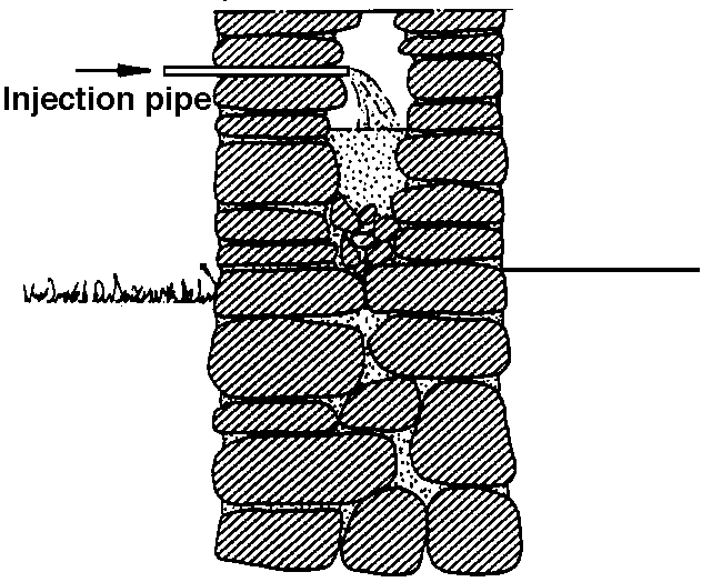
215 Injecting mortar
This method may be used in the middle room of a box foundation. Mortar injection strengthens the wall and reduces damaging moisture penetration. The loose mass inside the wall should be removed to the greatest extent possible by excavation or flushing with water. The cement mortar is injected through openings in the outer wall. Numerous openings will give the best distribution of the water (see Figure 215).
22 Preventing frost damage
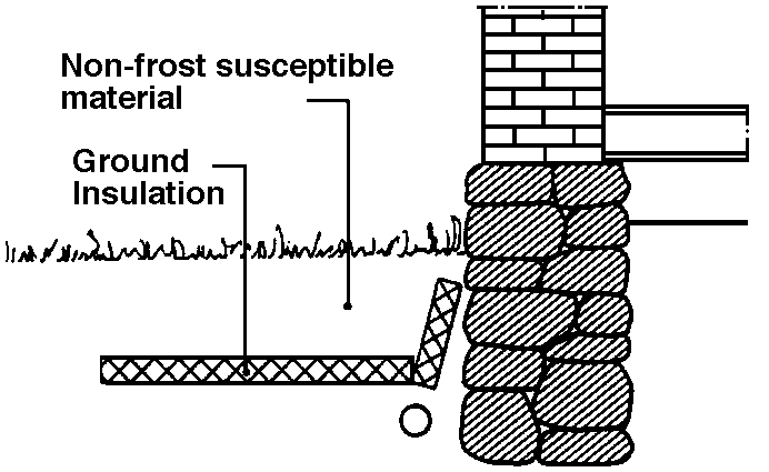
Movement in the foundation/foundation wall as a result of frost action can often be prevented or reduced by ground insulation laid out along the building. A problem with this is that old construction will act as a cold bridge where the frost can penetrate down regardless of insulation (Figure 22).
23 Raising the groundwater table
Raising the groundwater table can protect the existing support system of wood from damage in areas where the water table is shrinking. The wood must be healthy at the start, however, otherwise the method has little going for it. In areas where settling is occurring, it may be desirable to stop this by increasing the poor pressure in the soil. This method requires infiltration through permeable soils since a local increase in water table will normally not be sufficient to raise the groundwater table in dense soil masses.
231 Controlled watering
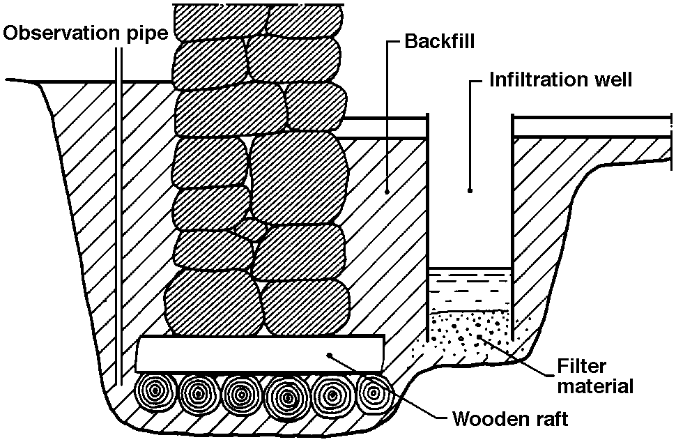
In this method the upper groundwater storage aquifer is filled to prevent exposure of the wood in rafts above the water surface. A well is dug next to the wall, down to the upper part of the raft. The well must be supplied with water so that the water table always covers the wood. This can be maintained by installing an automatic leveling regulator. Several observation pipes must be installed along the circumference of the building to control the water level. Controlled watering requires a permanent survey system.
232 Removing large trees
If large deciduous trees are next to the foundation wall, the roots can absorb so much water that the local groundwater table is drawn down.
233 Infiltration
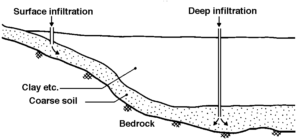
Surface infiltration is done by connecting shallow wells or pipes to the water bearing layer (see Figure 233).
Deep infiltration is done through shafts in rock or through pipes that extend down to the actual depth of the water table. The water must normally be supplied under significant overpressure with respect to the existing pore water pressure.
Infiltration must be monitored by installing pore pressure meters (Piezometers) in the ground. Shafts and pipes must be constructed so that they can be cleaned on a regular basis.
A permanent infiltration system is difficult to maintain and must be planned by specialists. Practical experience from Norway is limited.
24 Constructing a dry wall
Small walls are, as a rule, easy to repair, but they must first be secured against further damage, for example, by placing ground insulation under them. See Point 22.
Rocks that have fallen out and rock that has been displaced must be removed. With larger walls, one must determine what kind of construction should be used before the wall work commences.
25 Reinforcing drywall with concrete and reinforcing steel
Drywall foundations were originally thought to conduct vertical loads only from the walls to the ground or raft. Local settling, rot in raft foundations, and so on can make it desirable to strengthen the wall so that it can take lateral as well as vertical stress. Such strengthening can be combined with piling along the foundation. See Point 28.
251 Concrete Beams
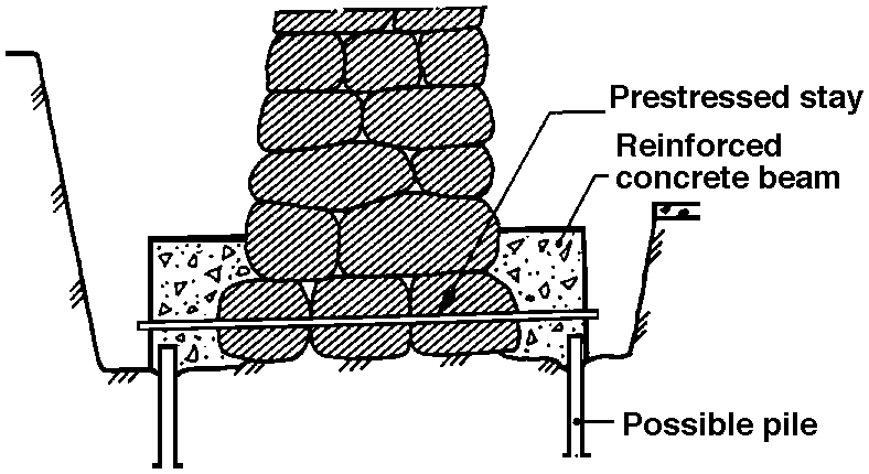
If there is plenty of room and if it is possible to dig down on either side of the wall, the simplest strengthening method is to pour a reinforced concrete beam on either side of the wall. These beams, take over the whole support function and tie in with prestressed stays or by cross bracing through the wall. If much stress are expected, the new beams may require quite a bit of room. Strengthening with concrete beams can also be combined with piling. See Figure 251.
252 Shotcrete
This method requires digging down on both sides of the wall so that it can be cleaned on the surface. Loose materials can be removed by scraping and washing. Shotcrete is sprayed on the mortared side in relatively thick layers. For extra strength fiber reinforced shotcrete should be used. Tension and shear reinforcement must be put into the concrete. Through-the-wall holes can be drilled for cross-bracing, and they may be prestressed. The braces must be rust protected. See Figure 252.
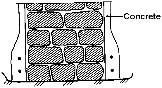
253 Shotcrete and injection
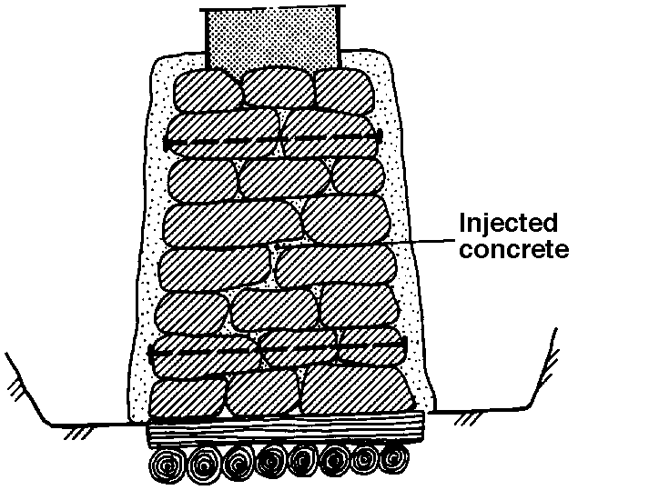
If the dry wall is made of poorly matched rocks one can, in addition to the strengthening described in Point 252, inject concrete into the hollow spaces between the rocks. If this method is used piles must be placed, rinsed, and injected into the outer concrete layer which, after hardening, acts as a reinforcing box.
Cleanse the wall inside via the pipes. Concrete is then injected so that as much of the inside hollow space as possible is filled. Both water pressure and concrete injection pressure ought to be at a moderate level. For concrete about 0.05-0.1 MN/m2. See Figure 253.
26 New concrete foundation/underpinning
261 Point foundations
The loose, and often course, rock that is found under the corners of rafted houses is often exposed to settling and movement because of frost. The house should be lifted back to the original elevation. The point foundation can then be removed temporarily while a pressure distributing concrete slab is poured to frost free depth. The point foundation is then reconstructed after the old pattern. Rock that does not fit very well should be encased in mortar (see Figure 261).
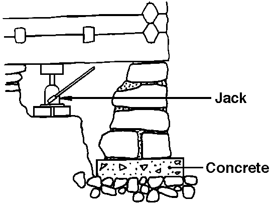
Alternatively, the foundation can be secured against frost damage as discussed in Point 22.
With especially poor soil conditions, a continuous foundation can be poured to the level of the terrain. Above the terrain, mortar work is done with natural rock. See Point 263.
262 Underpinning
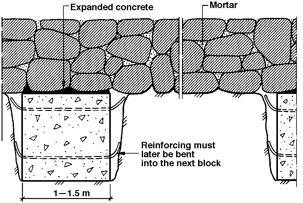
Underpinning can be used only in foundations which have a certain amount of internal strength. For example it can be used in sections where the foundation or foundation wall has been mortared together or in sections which have already been reinforced. To underpin, one should dig down on both sides of the wall. Then remove the material underneath the foundation in sections. The length of the sections being removed must be adjusted depending on what the old wall can tolerate. Normal length is 1 to 1.5 meters. Settling must be anticipated, and underpinning should be continued along the whole wall to avoid uneven settlement. When the material has been removed to the desired depth and width, the reinforcing and falsework are placed. Reinforcing should be made longer than the sections and be bent to the sides so that it can be spliced with the next section when this section is being poured. Under some circumstances, the soil side can be used as false work. A layer of expanding concrete is placed on the completed poured section to prevent building settlement while the intermediate parts are being re-excavated and poured (Figure 262).
263 New ringwall
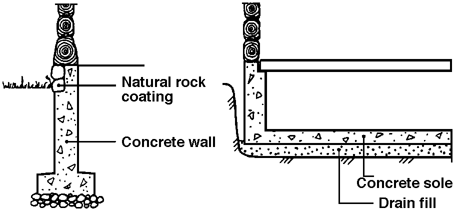
A new concrete ringwall should be used only when the foundation or foundation wall is in such poor condition that it is not worth saving. Wooden buildings can be jacked up and renovated while the old foundation and foundation wall are being removed. Dig down to frost free depth to bearing ground before a new foundation is poured or rebuilt, for example, with lightweight concrete blocks. The part of the foundation wall which is visible ought to be surface treated or treated so that the wall looks like the original (Figure 263).
264 Concrete slab
Pouring a whole slab of concrete under the entire building can be used in circumstances where the foundation must be rebuilt anyway. For instance, a concrete slab may be desirable if the building is going to take large loads on the first floor, or if the basement floor is destroyed. This method can also be considered as an alternative to pilings when difficult soil conditions are present (Figure 264).
Wooden buildings can be jacked up and relocated so that the old floor and foundation wall can be removed. The ground should be leveled and drained if necessary. The concrete slab with ringwall is poured on a foundation of drained fill with adequate load-bearing capacity. The house is then jacked back in place. With brick buildings, the whole slab can be poured in sections.
27 Repairing existing piles
This method consists of replacing rotting wooden portions with steel or concrete piles. Repairing existing piles must take place in steps. Missing information about the number of piles, dimensions, lengths, bearing capacity, and so on makes the planning of such a job quite difficult.
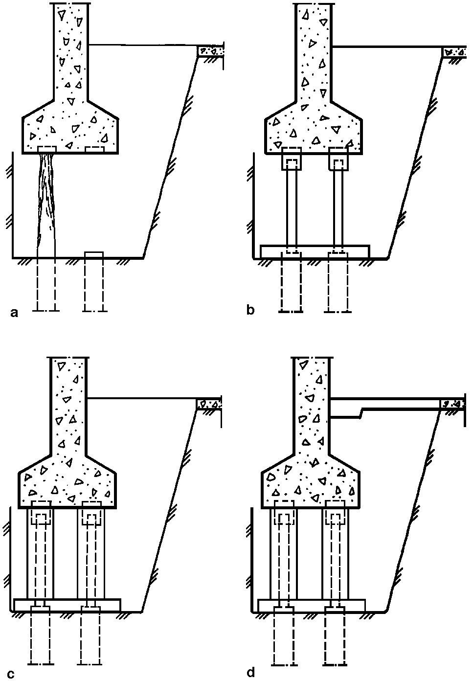
Dig down in sections along the wall to a point where it is possible to remove the remains of rotten rafts. Then cut the old piles some distance under the water table, taking into account possible further lowering of the water level (Figure 27a).
Place new piles between the foundation walls and/or pad and the top of the cutoff piles. Use piles of concrete or steel. Steel piles must be corrosion protected with plastic asphalt or concrete or have room for corrosion. Ensure that there will be an even distribution of the forces from the wall. The joints must be strong enough to ensure that the new piles will be rigid in terms of stress transfer. This can be done by pouring the concrete pad over the old piles (Figure 27 b-d).
28 Piling
281 General
Many piles and piling methods have been developed. When doing refoundation work it is often necessary to push down the piles or ram them down with a light air hammer. Another method is to install piles in drilled sleeves. Both pushing piles and ramming piles with a light air hammer requires that the soil is homogeneous. It is very important to look for solid mineral soil and rocks in the ground, to map the rock types, and to be aware of inclined rock surfaces. It is also very important to recognize alum shales and to know where erosive groundwater exists. Installing piles requires thorough technical evaluation and planning. For example, placing piles next to foundation wall, establishing a foothold, evaluating of rock bearing strength and straightness of the pile can all affect the success of the foundation. It is also necessary to take into account possible damage to the structure by excavation and reestablishment of loads. There are examples given of several pile types that can be used. Figure 282a to 282b.
282 Driven or rammed steel piles
There are several types of driven or rammed steel piles, including rolled steel piles, light, hollow steel piles, steel profiles, and steel pipe piles.
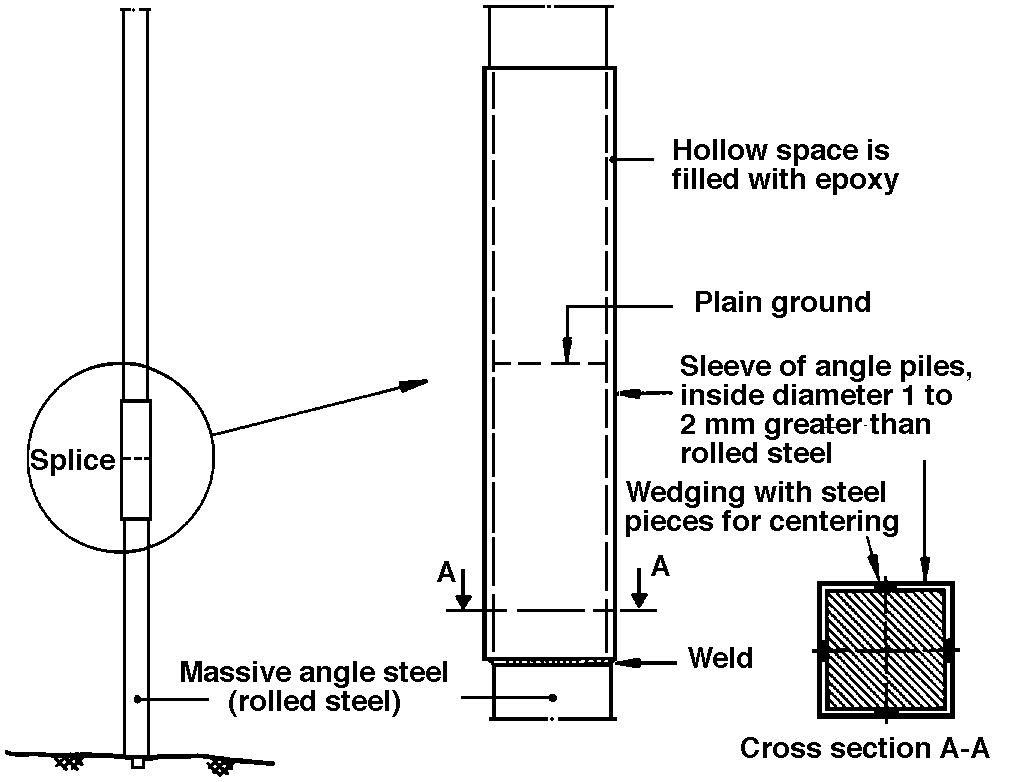
Use rolled steel with steel quality ST37 with variable cross section (i.e. 40 mm x 40 mm to 120 mm x 120 mm). The pile length should vary between 1.5 m and 2 m. The point on the pile should be hardened, axle steel. The piles can be spliced at each pile segment in the upper end and welded on a box of angle steel with a length of about 500 mm of which 250 mm should protrude above the top of the pile segment. There should be a clearing between the rolled steel segment and the sleeve of angle iron of about 1 to 2 mm. The sleeve can be centered in the length of the pile by wedging it with steel pieces. See Figure 282a. The sleeve is then filled with a small amount of epoxy and the next pile is mounted so that the epoxy flows out into the hollow space between the rolled steel piece and the sleeve of angle steel. The overlying pile segment is centered with steel wedges, and the sleeve is warmed up to about 40°C to get a rapid hardening of the epoxy. This type of pile is quite suitable for use with homogeneous soil conditions. The joint is not, however, particularly movement resistant, and because of the small surface area, the pile is not very sensitive to corrosion. The pile has, however, a relatively large load capacity. For piling work, the roof height in the basement should be at least 2.5 m; however, with short pile segments the room height can be as low as 2 m. The smallest distance from the wall to center of a pile should be 150 mm.
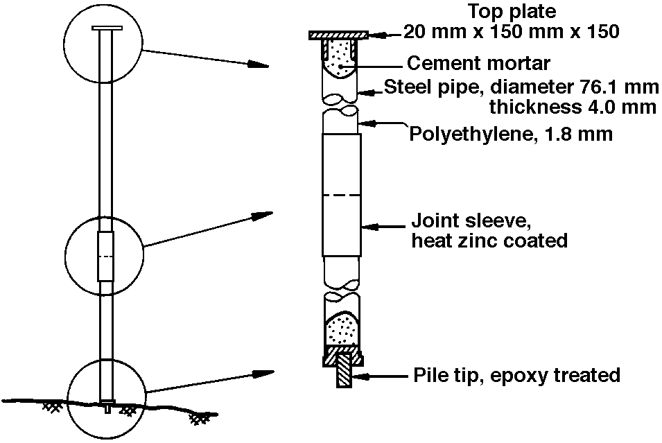
There are numerous light hollow pile types on the market. An example is the steel plastic pile which has a diameter of 76.1 mm and a wall thickness of 4 mm. The steel quality is ST52. Externally the pile is rust protected with a 1.8 nicron thick layer of polyethylene. (Figure 282b). The pile comes with an epoxy treated pile edge. The top plate consists of a steel plate with a pipe welded on and fitted to the inner diameter of the pile. The joint consists of an concentric sleeve with a wall thickness of 3.65 mm. The sleeve is threaded in place by a layer of polyethylene on the joint. The polyethylene is fused at the adjoining pile ends by heating it up. The sleeve is heat-shrunk to 80 microns in thickness. After the pile is installed, the inside volume is filled with concrete. The pile is quite easy to handle. It can be driven with an air hammer and is easy to use under tight conditions. The hollow space inside the pile makes it possible to control its straightness. The joint must be set to be movement stiff. The steel cross-section is, however, only 950 mm2, and the load capacity is, therefore, limited. The necessary height for the rig is about 2.1 m. The center pile should be placed 150 mm from the edge of the wall.
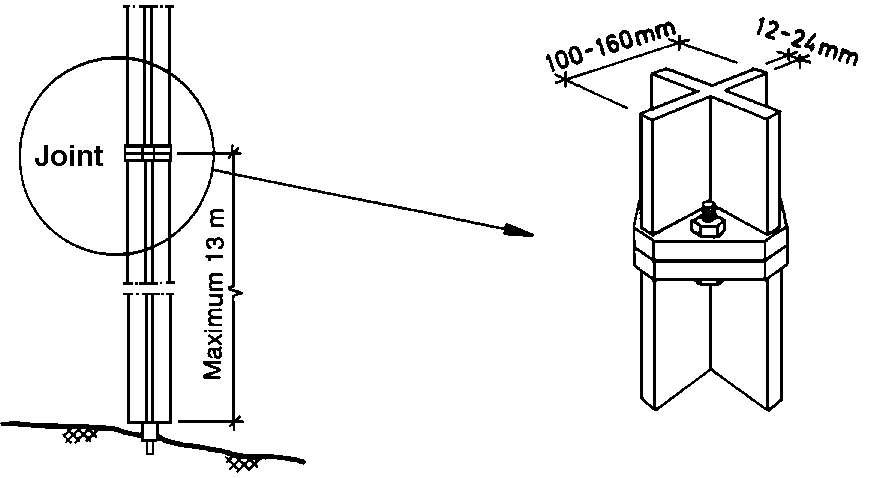
There are many steel profiles in use. Streetcar and railroad tracks have been used with good results. A special profile is the so-called SW-steel pile which has a cross-shaped cross-section, which gives the pile a relatively large bending resistance with respect to the area. It is available in three sizes with cross-sections of 2,600, 6,100 or 8,100 mm2. The steel quality is ST37 (see Figure 282c). The pile is provided with a pile point and a top plate of steel. The top plate is fixed, either with guide ribs or by welding, to the center portion of the pile. The pile is joined at each pile end, being welded to a steel plate so that the connection can be established with four bolts. The joint is relatively shear resistant. The smallest pile can be driven down with a light air hammer. The larger types demand a greater ram capacity. The piles are normally delivered untreated, and they will, because of their large surface area, be somewhat subject to corrosion.
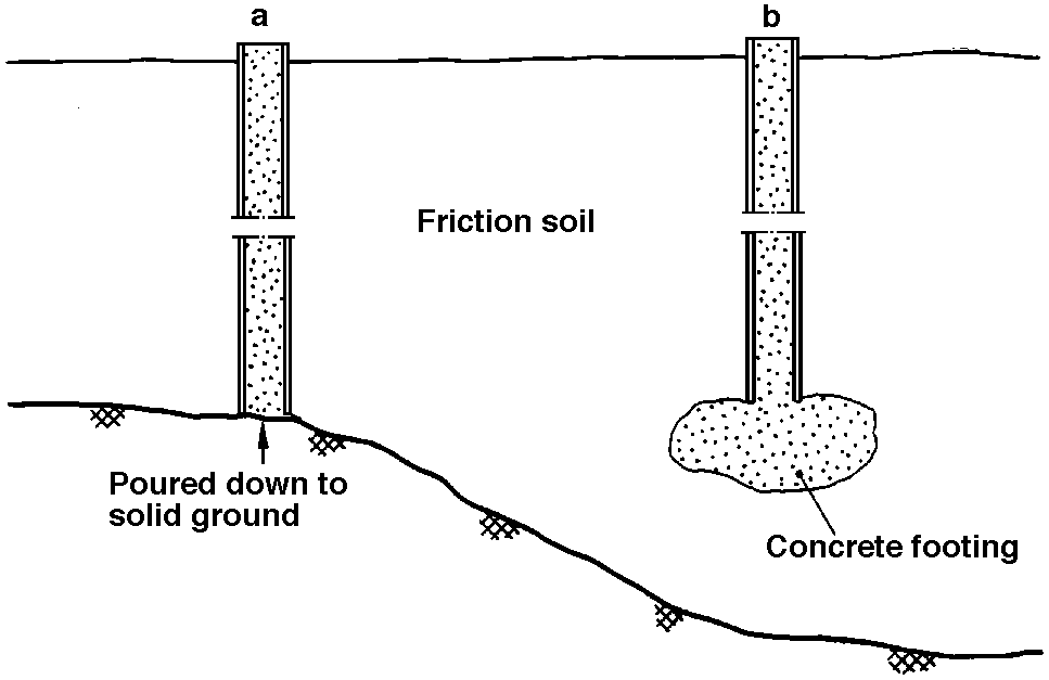
The megasteel pile is a square steel pipe pile which is pushed down into the soil with a hydraulic jack while the soil mass is being flushed away from the edge of the pile. If the soil is difficult to hose away with water it can be drilled down through the pipe. The joints are made by welding. The piles can be pushed down and supported on solid rock or a small man-made concrete lump in the soil. In the latter case, the pipe is rammed to a desired level and concrete is pumped into the soil to create a massive bearing surface under the pile. This method can be used only in friction soils which can be penetrated easily enough for concrete to be injected. When the concrete has hardened and has full bearing capacity, the rest of the pile is filled with concrete. The pile can be dimensioned as if it consisted only of steel. The concrete protects against corrosion and should prevent bending. When calculating capacity, take into consideration the external corrosion and the danger of concrete breaking in loose soils (see Figure 282d).
283 Pressed or driven concrete piles
There are two types of pressed or driven concrete piles: normal, joinable, prefabricated piles, and special piles.
Normal, joinable, prefabricated piles can be adjusted for refoundation work. They are useful when there is room to ram piles down on the outer perimeter of the building. Such piles can also be rammed or pressed down inside buildings. Because they have joints, the length of the pile element and the stress capacity of each pile must be calculated in each individual case.
An example of a special pile is the megapile which is rammed into place by hydraulic jacks. The building itself can be used as a counter balance. This method is often used on large buildings built on easily penetrable soil masses. The pile is usually square with a cross-section of about 300 mm. The length is about 1 m, but many lengths are available. The pile has a sentry hole, which makes it possible to control its direction during the placement process (see Figure 283).
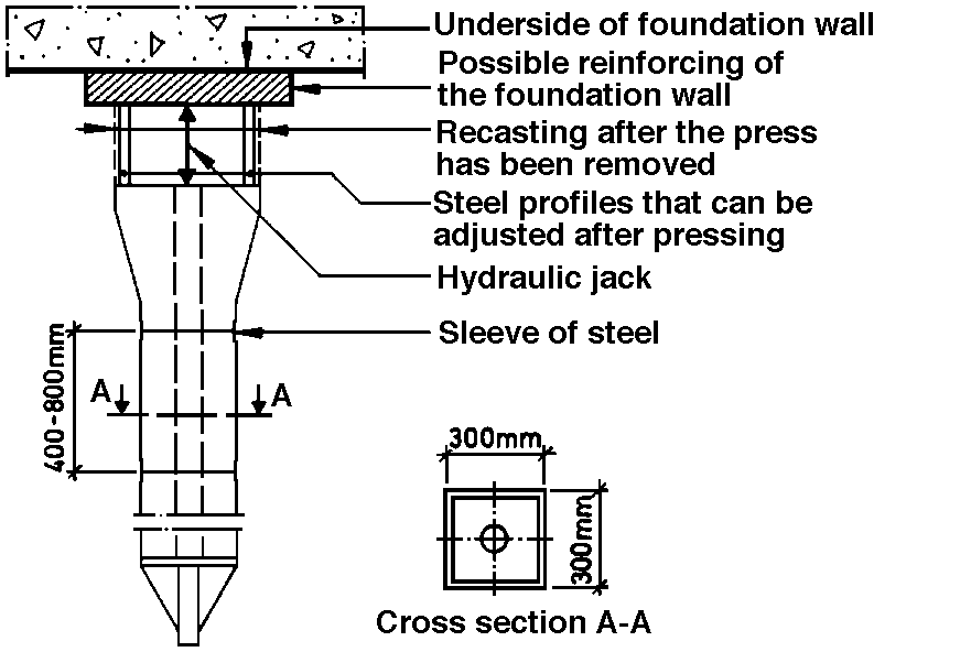
Splicing can be carried out in several ways. A single sleeve around the joint will prevent twisting and eccentricity between the piles; a threaded steel pipe along the center of the piles with the joint will give adequate bending capacity; and rigidly mounted steel plates that can be welded together at the ends of the piles will give a joint that is resistant to movements, but they are quite expensive.
In silt or sandy soil the center hole can be flushed through with water or air pressure to aid in the driving process. There is also equipment available for predrilling in areas where there are large rocks and other obstacles in the ground. Downshafting underneath the foundation of the building normally provides resistance for pushing down of the piles. Normal excavation depth under the foundation is about 1.5 m.
284 Board piles
Two types of board piles are used, steel core piles and injected concrete piles. Steelcore piles are used in solid rock. The Lindo pile is an example. Because of its high price, it should be used only where large rocks and other obstacles in the ground make it difficult to press down piles without predrilling. The pile consists of a round steel core which is surrounded by concrete and covered by a sleeve (see Figure 284). The diameter of the steel core varies between 50 and 100 mm with a steel cross-section between about 19.60 and 78.50 mm square. The steel quality is ST50 enabling the load capacity to cover a wide area. An eccentric drill bit is used to drill the steel pile down to solid ground. The pipe is drilled down into bedrock a small distance so it will have a good seat. Pipe length can be 1 to 3 m, depending on how much height one has to work with. Different pipe lengths can be screwed or welded together.
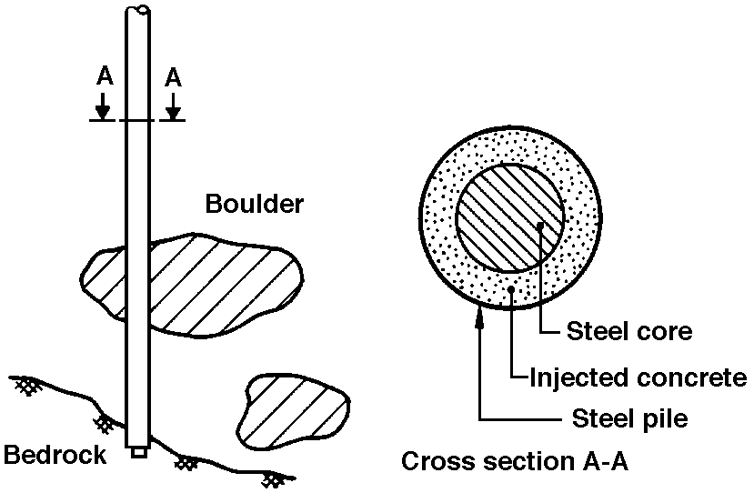
After the pipe is in place is filled with concrete mortar. The concrete will corrosion-proof the bearing element in the pile. The core consists of massive steel rods in suitable length which are being spliced together with welds or threaded sleeves. The rods are placed immediately after pouring of the concrete. There are special machines for boring in narrow and low rooms.
Injected concrete piles are used as friction piles in circumstances where the load is carried down to bearing soil layers. An example of such a pile is the so-called root pile, which is used in Sweden and elsewhere in Europe. This pile uses an aggregate with a 1.8 m work height and is drilled down 1 m using spliceable steel piles. The bottom pipe is connected with a large powerful shear ring. Loose material is transported upwards while the pipe is being bored by a spray of bentonite or water under high pressure. When the desired pile depth has been reached, prefabricated reinforcing baskets are sunk and welded as they come down into the tube. An aerated concrete is then poured down into the pipe through a hose, as with conventional underwater pouring. A closed lid is mounted on the top of the pile and the concrete is pressurized. Finally, the pipe is pulled up in sections as the tube pile is locked and the concrete is pressurized. This assures that the pile will adhere well with the surrounding soil and provide a high carrying capacity.
285 Other piles. Wooden piles and wing piles are also useful with refoundation work
Unfortunately, wooden piles must be completely submerged to keep from rotting. If wood is exposed to variable humidity above the groundwater table, it will rot very quickly. However, for certain kinds of buildings such as piers and houses that are next to the sea, wooden piles are still the best type of foundation. Wooden piles are inexpensive, but they should be straight and they must be prepared well. The bark must be removed and branches cut off close to the trunk. The top diameter must not be less than 150 mm. The pile is driven with the top down. It is important to use piles impregnated with preservative, such as creosote. (See Figure 285a).
In Sweden, a cohesion pile has been developed which consists of a relatively thin steel pipe with long longitudinal ribs. The length of the piles joined with the sleeve can vary according to building conditions. Figure 285b. The advantage of a cohesion pile lies in its great bending resistance and its cohesive surface qualities with respect to the displaced soil material. Driving is done with a light air hammer or vibration hammers. There is, however, little experience with this system.
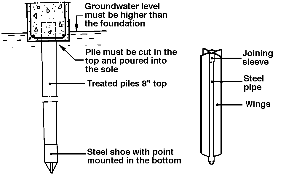
286 Load transmission
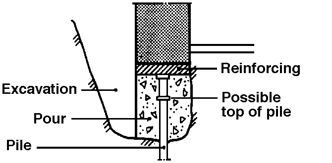
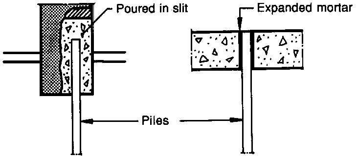
Load transmission from pile to structure can be arranged in several ways. One method is to dig under the foundation wall and place the pile directly under the foundation wall. The forces from the structure to the pile will then be transmitted directly or via a board cap on top of the pile. (Figure 286a). Another method of load transmission is through slits in the foundation wall and/or the foundation. The pile is placed inside the slit and concrete poured around it. The forces from the building are transmitted to the pile by cohesion forces. The same principle can be used with piles installed in bored holes using heavy construction foundation plates. (Figure 286b).
Load transmission can also be accomplished by a pile, or piles, placed on either side of the foundation wall. A beam (i.e. a steel beam with concrete) placed over the piles and in direct contact with the lower portion of the foundation establish a beam which will transmit the load to the pile (Figure 286c).
Piles can be driven on either side of the foundation wall for load transmission. A beam is poured on either side of the foundation wall over the piles. The load from the foundation wall to the concrete beam is transferred by cross beams (i.e. poured steel beams or ties). The force in the ties should be checked to be sure that the friction is sufficient (Figure 286d).

29 Replacement of material
Around buildings where there is consolidation settling, it is possible to replace existing fills with lighter fills such as lightweight concrete or sawdust.
3 REFERENCES
31 This bulletin has been developed by Knut I. Edvardsen, Norwegian Building Research Institute. Svein Bjorberg, Multiconsult A/S and Arne Nesje, Mur-sentret. Rolf Hauan, Engineers Bonde & Co. and Bjorn Finborud, NOTEBY have been consultants.
The editing was completed September 1981.
32 Literature
321 Translated into English by Nils Johanson and Richard D. Seifert, University of Alaska Fairbanks, 1989.
Art Nash, Extension Energy Specialist; originally translated by Richard Seifert, former Extension Energy and Housing Specialist
Reviewed September 2021
