Assembling a Can Sealer
FNH-00022 View this publication in PDF form to print or download.
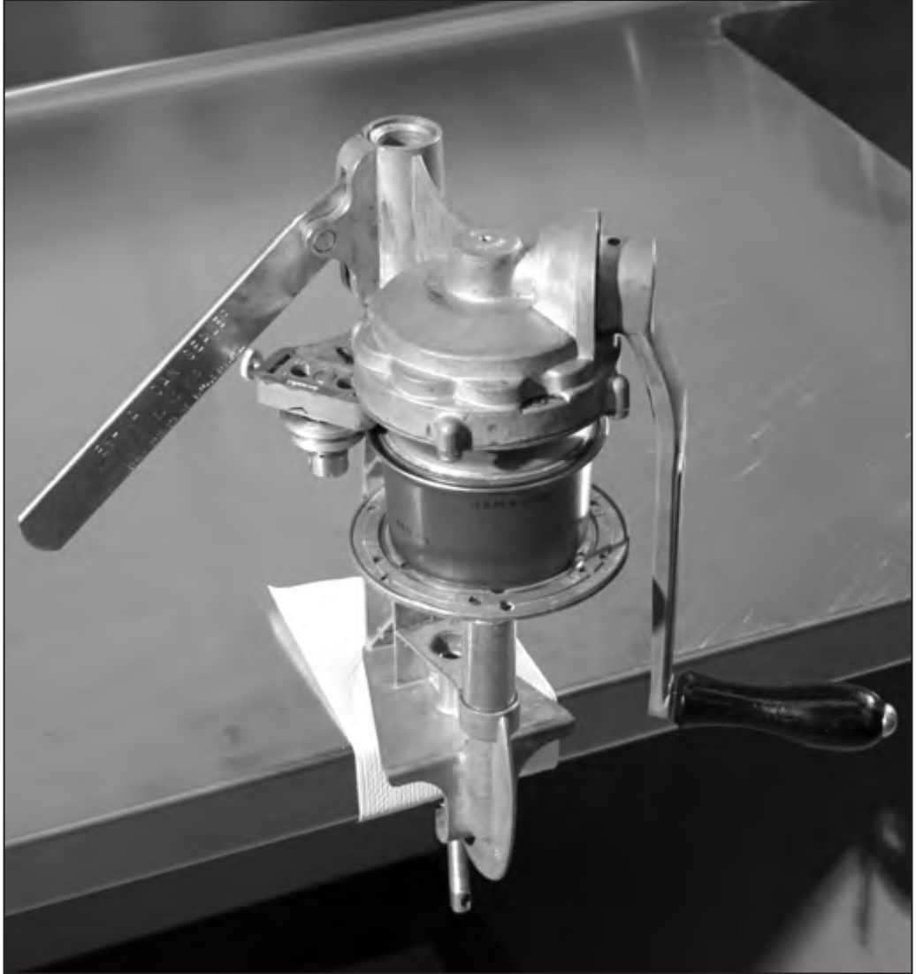
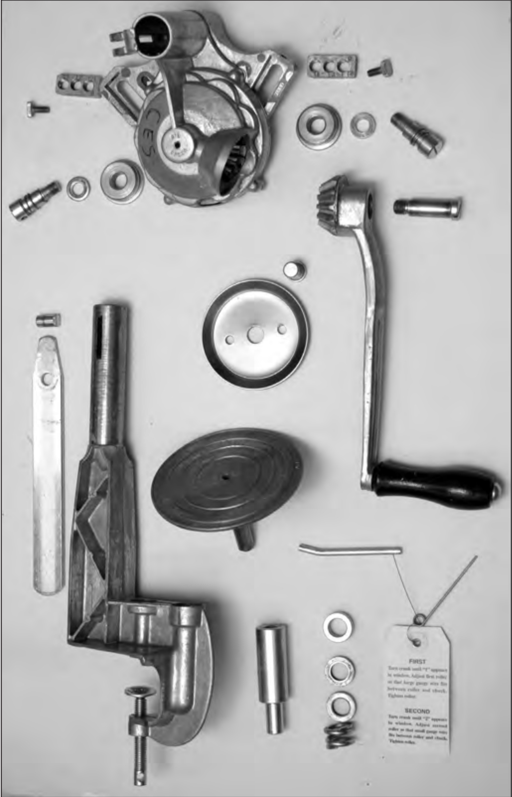
This publication is a step-by-step guidebook for the assembly and preparation of a can sealer. The identification of all sealer parts is clearly presented, and easy-to-understand instructions include photographs illustrating the procedure.
|
|
Can Sealer Parts
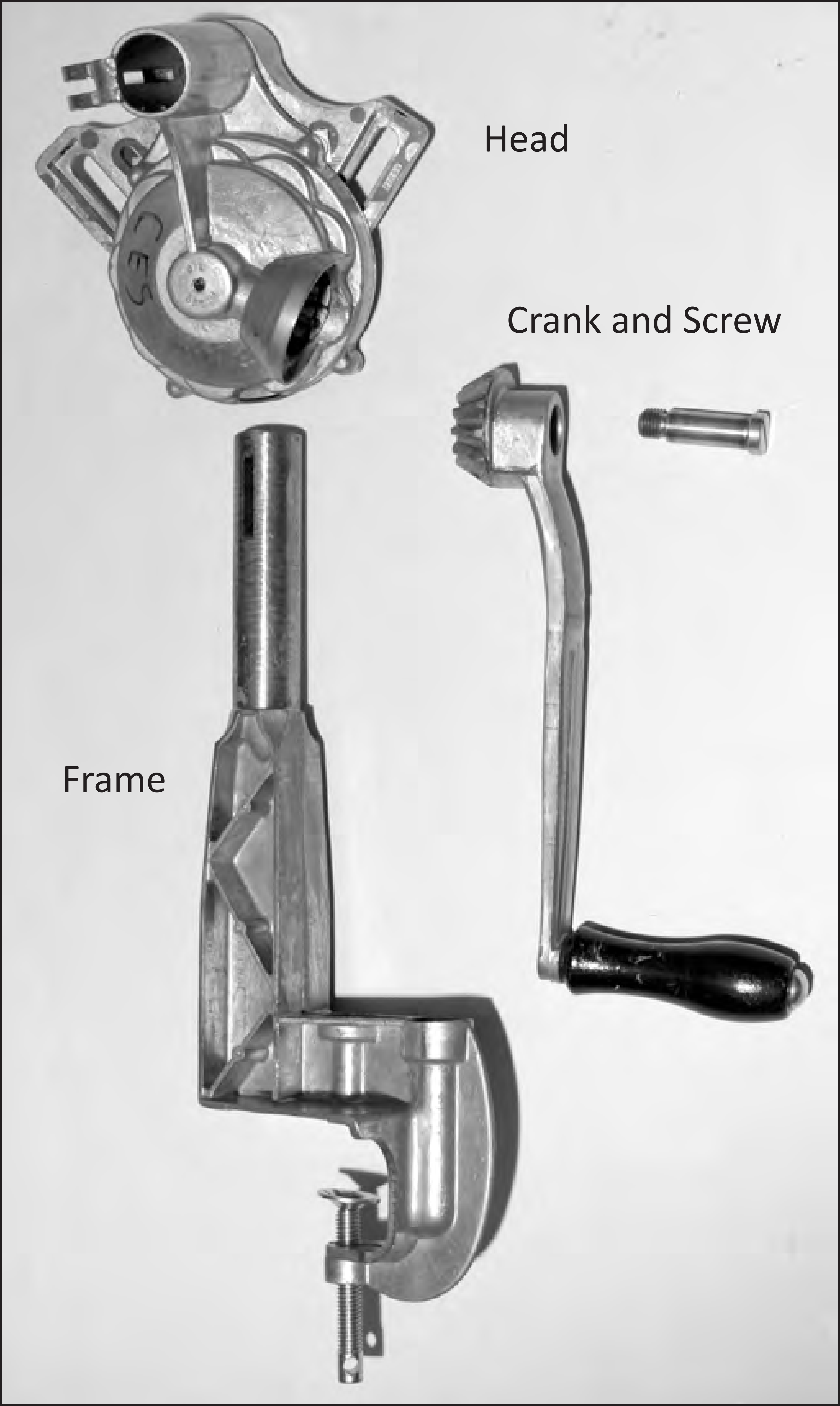 |
|

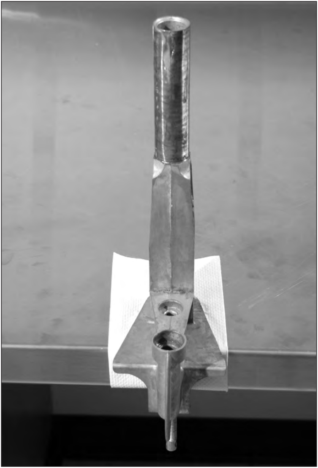
1. Situate the Frame
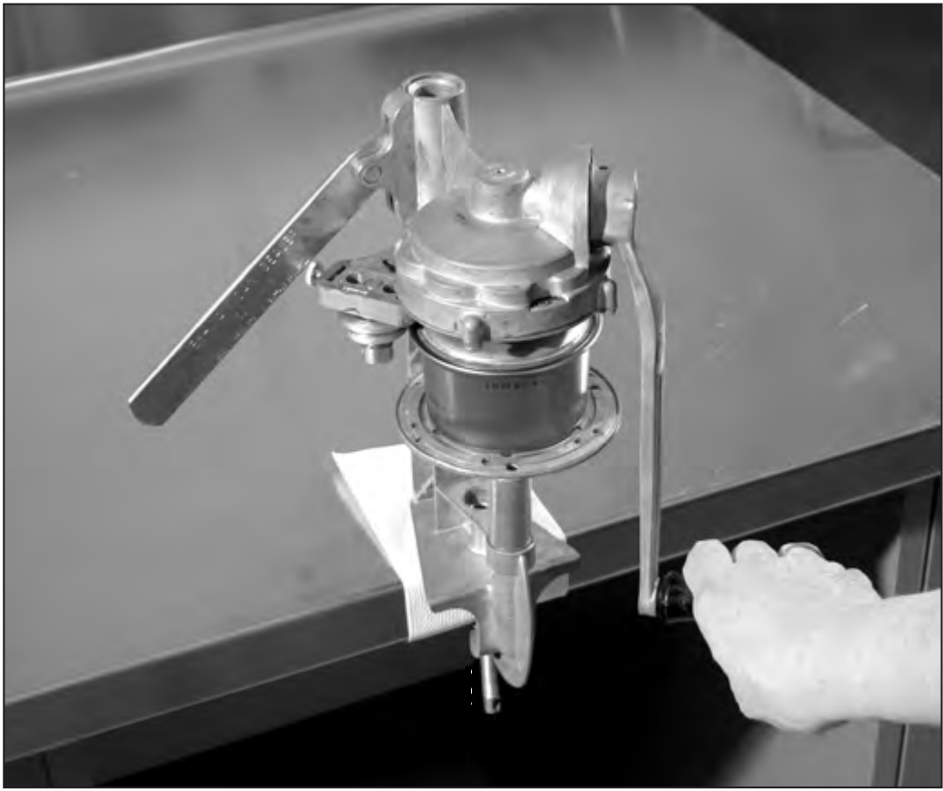
Start by clamping the frame securely to a table. Use the 3-inch pin to tighten the clamp screw. Use a cloth or a piece of cardboard to protect the surface of your table.
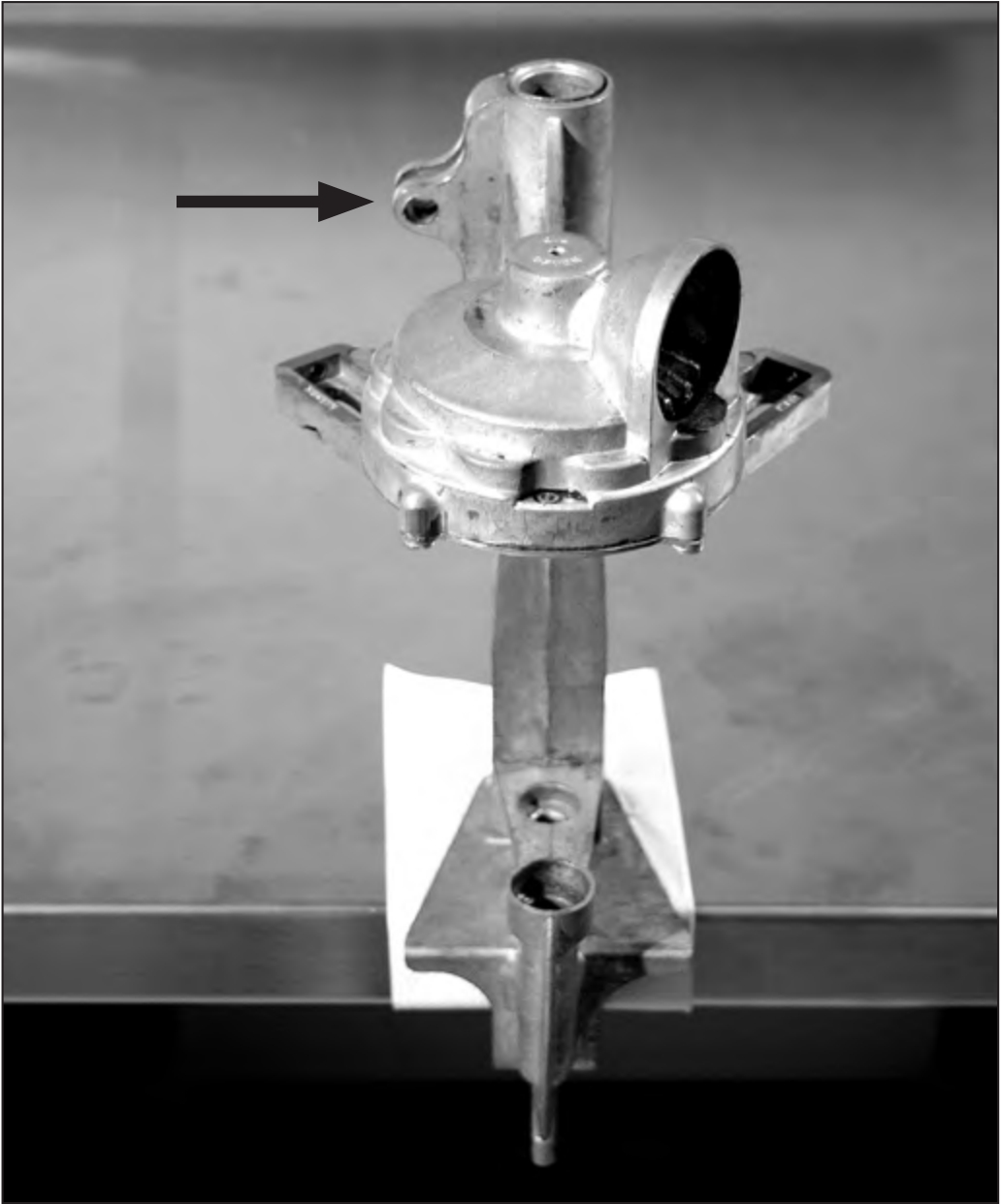
2. Place the Head on the Frame
The head drops onto the frame. Notice that there is a slot in both the head and in the post of the frame (arrow).
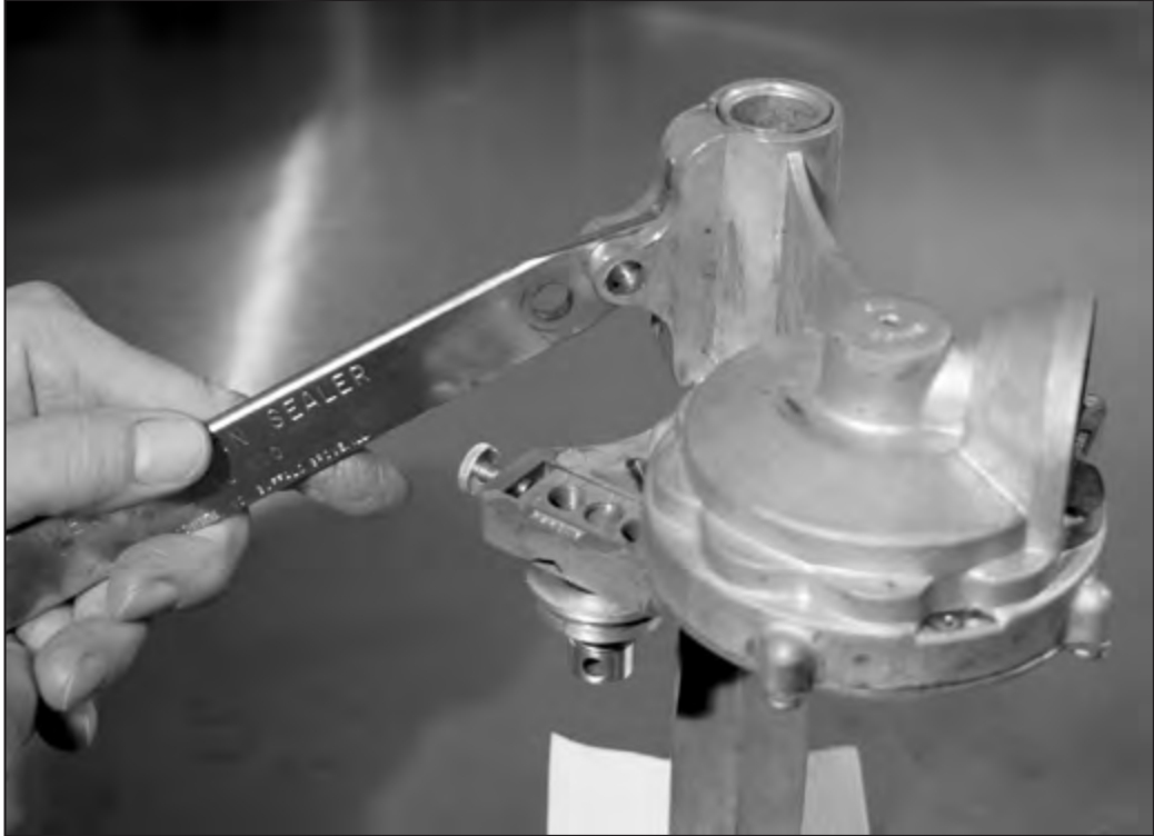
3. The Lever
Place the head on the frame post. Align slot in the head with the slot in the frame. Insert the lever into the slot (writing should face forward). Line up the hole in the lever with the two holes in the head.
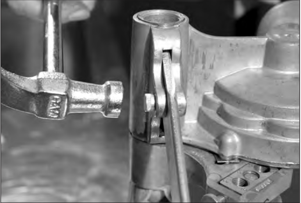
4. Insert the Lever Pivot
Insert the lever pivot from the back — knurled (ridged) side of the pivot out. Tap in the lever pivot with a hammer.
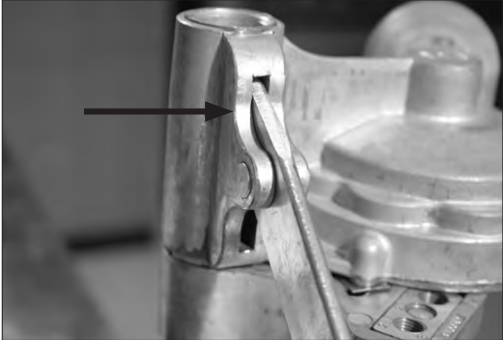
5. Seat the Lever Pivot
The lever pivot should be flush with the backside of the head (arrow).
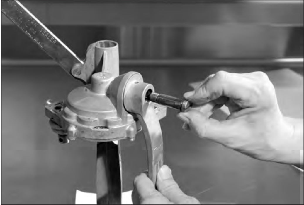
6. Attach the Crank
Insert the gear end of the crank into the head. Thread the screw.
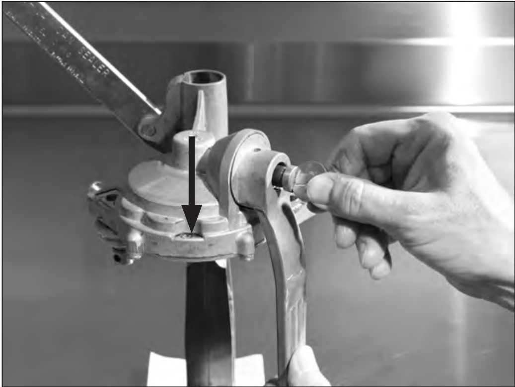
7. Set Crank Position
Finger tighten the screw. Turn the crank handle until the “0” appears in the center of the indicating window (arrow).
Loosen the crank screw and reposition the crank handle so it hangs straight down. Tighten the crank screw with a coin (a quarter works well).
Choosing Can Sizes
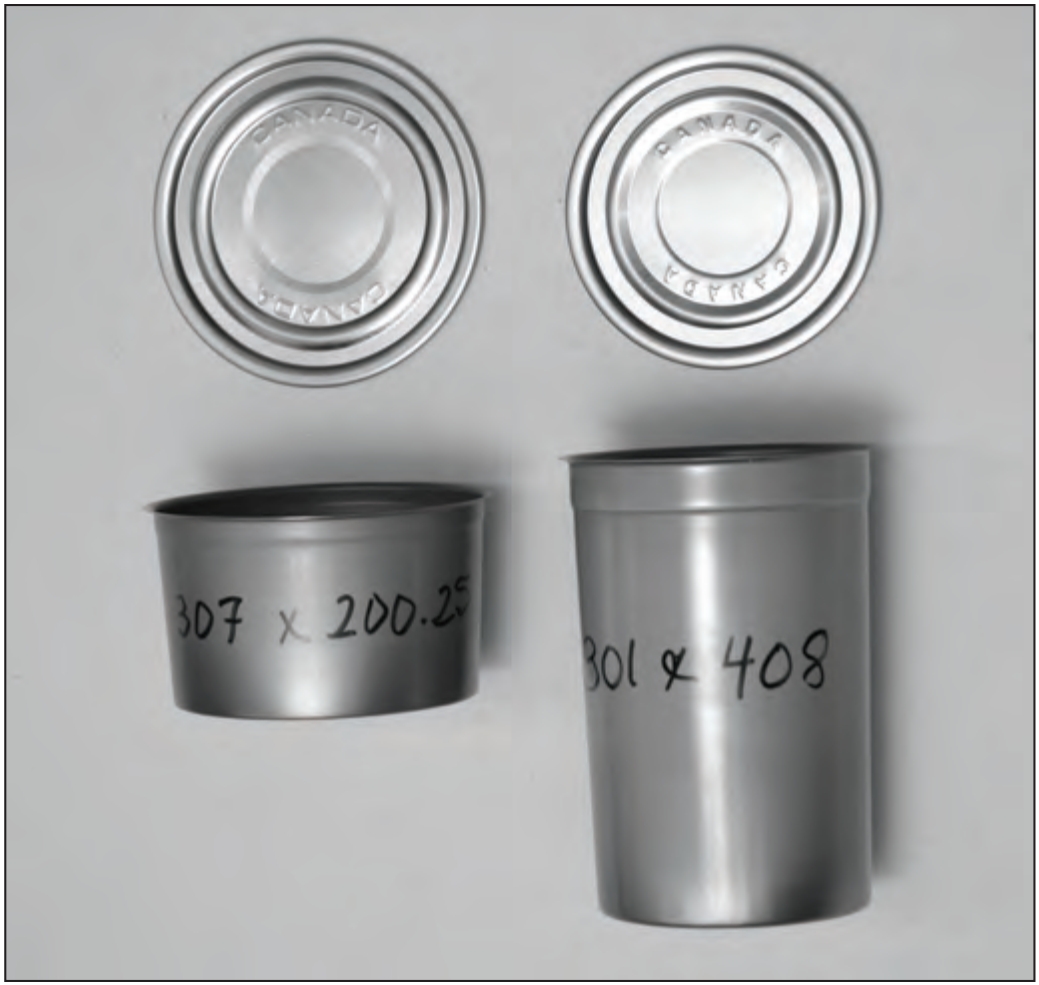
To assemble the sealer, you will need to identify the can size you will be using (diameter and height). The size of the can will determine the following:
- chuck size
- position of the seaming rollers
- number and size of spacers used with the turntable spring and turntable
- turntable extension
|
|
Salmon Can Specifics
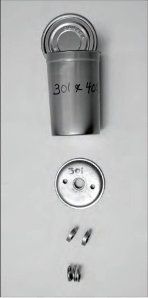
Tall, 1-pound, 301 x 408 cans use
- #301 chuck
- #2 hole in the 3-hole nut
- two 3⁄16-inch turntable spacers and turntable spring
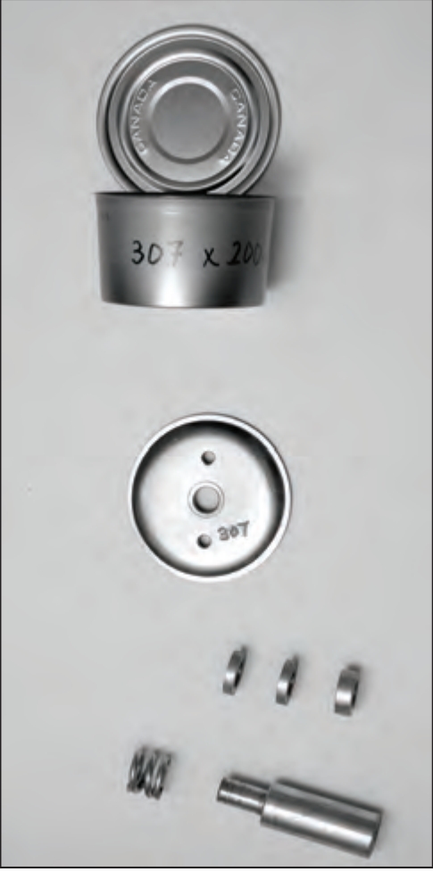
Flat, ½-pound, 307 x 200.25 cans use
- #307 chuck
- #2 hole in the 3-hole nut
- two 3 ⁄16-inch spacers, one 5 ⁄16-inch spacer
- turntable extension and turntable spring
The Three Hole Nuts
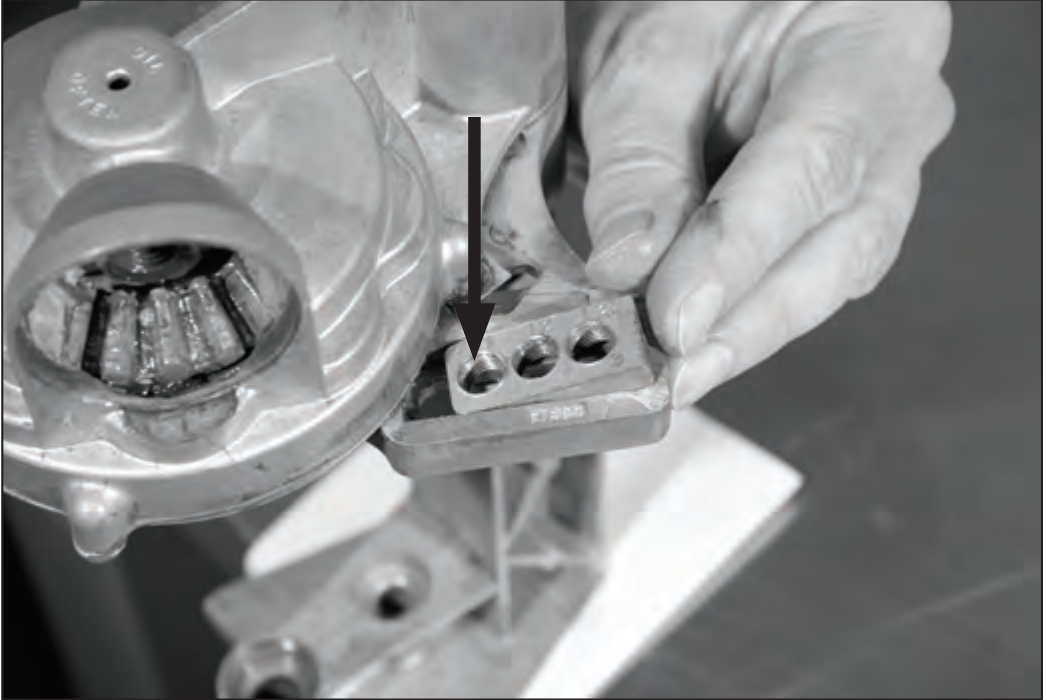
Right side: Insert the 3-hole nut in the channel labeled “first” on the right side of the head.
Numbers should be visible on the top of the nut. The “1” on the nut should be toward the center of the head (arrow).
Left side: Insert the 3-hole nut in the channel labeled “second” on the left side of the head.
Numbers should be visible on the top of the nut. The “1” on the nut should be toward the center of the head.
Slide the 3-hole nut back and forth in its track until it moves freely. A new sealer may have casting marks that obstruct free movement of the nut within the tracks. File these off, if any.
Identifying the Rollers
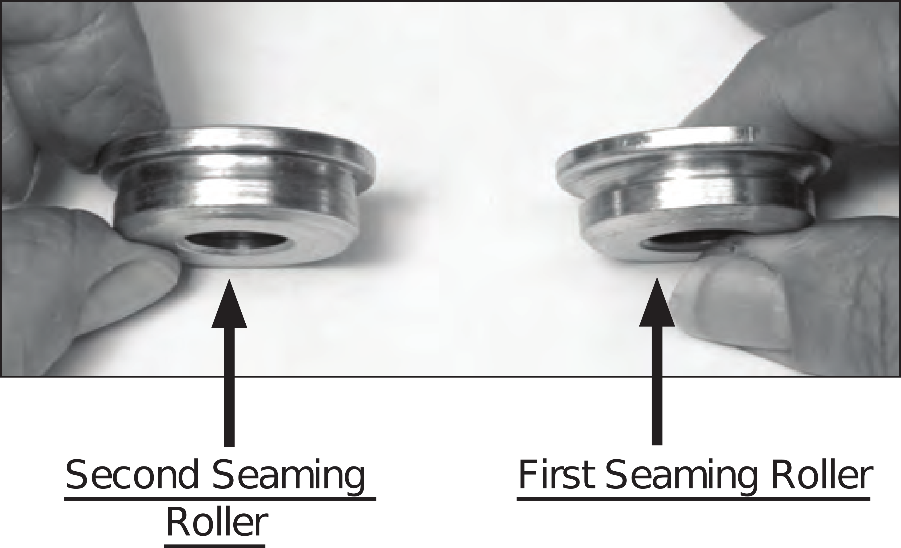
There are two seaming rollers. The “first” seaming roller is on the right side of the sealer and is for curling the lid and can body edges together. This roller has a deeper, more rounded profile.
The “second” seaming roller is on the left side of the sealer and is for flattening the seam. This roller has a shallower, flatter profile.
1. The First Roller Assembly
(right side of sealer head)
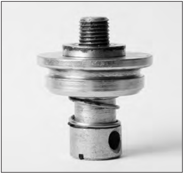
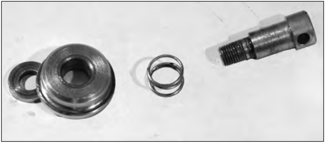
Make the first roller assembly by putting the spring onto the roller screw, then the seaming roller and then the washer. The largest part of the seaming roller is next to the washer.
 |
|
2. Attach the First Roller Assembly
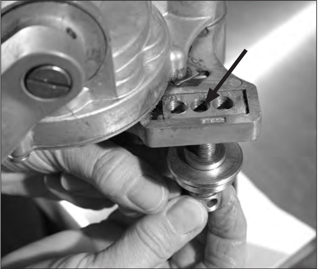
Loosely thread the first seaming roller assembly into the 3-hole nut from the bottom.
Salmon cans (tall, 1-pound cans and flat, ½-pound cans) use the #2 hole (arrow).
3. The Thumbscrew
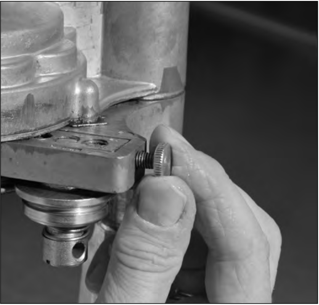
Thread in the thumbscrew loosely. Rotate the crank until the “1” appears in the indicating window.
4. The Second Seam Roller
(left side of sealer head)
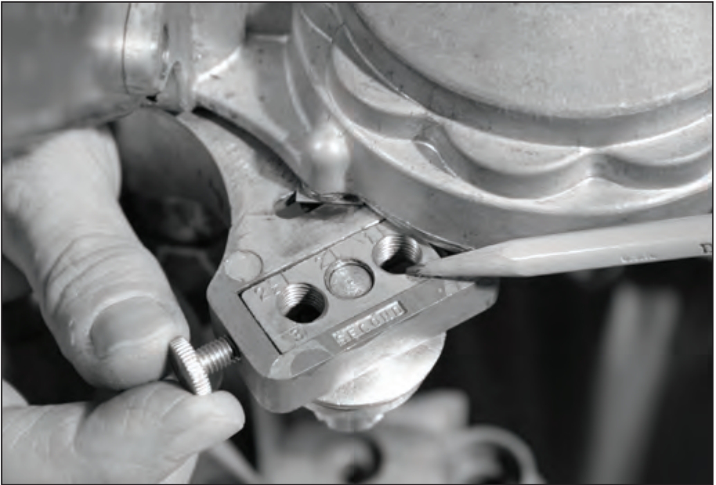
Rotate the crank until a “2” appears in the indicating window. Install the second seaming roller on the left side in the same manner as the first (see steps 1-3). Note the orientation of the 3-hole nut (pencil points to the #1 hole).
5. Attach the Chuck
Rotate the crank until the “0” appears in the indicating window. Select the appropriate chuck for the can size you will be using (see page 5). With the concave face of the chuck facing down, insert the chuck screw through the center of the chuck. Thread the screw into the head by hand. Do not use a screwdriver.
Make sure the thumbscrew and 3-hole nut are backed off or the chuck may not go on — it hangs up on rollers.
6. Tighten the Chuck
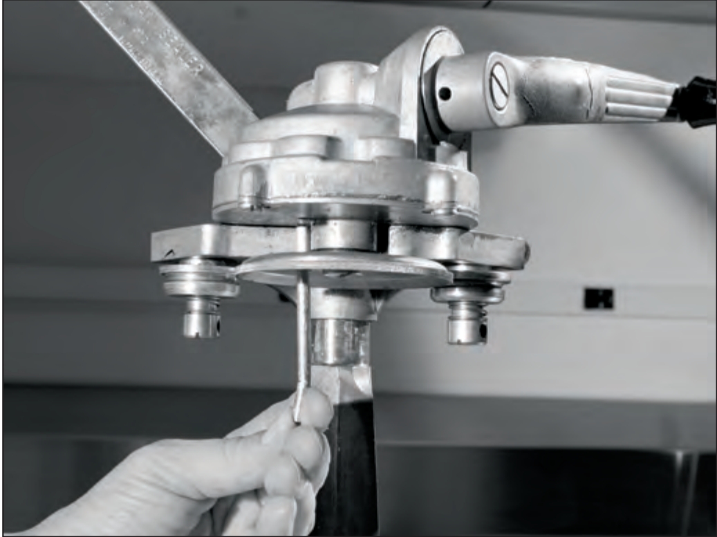
Insert the 3-inch pin into one of the small holes in the chuck. Turn the crank clockwise until the 3-inch pin is pressed against the frame and chuck is tight. Remove the pin.
To remove the chuck, follow the same directions except turn the crank counterclockwise.
Clockwise tightens.
Counterclockwise loosens.
7. Set the Seam Rollers
Accurately setting and securing both seam rollers is essential. The first and second gauge wires are used to set the distance between the rollers and the chucks. These settings control the shape and tightness of your can seams and, therefore, the quality of the hermetic seal. Since food must never be stored in cans that have improperly formed seams, an improperly adjusted can sealer has no role in food preservation.
8. Adjusting the First Seam Roller
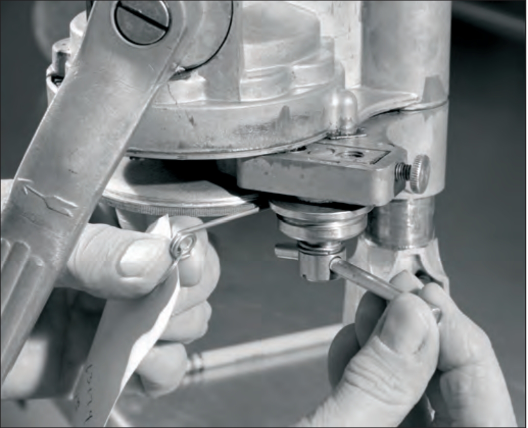
Back out the thumbscrew and slide the first seaming roller and 3-hole nut to the outside, hard against the frame (pencil point in photograph). The first roller is to the right.
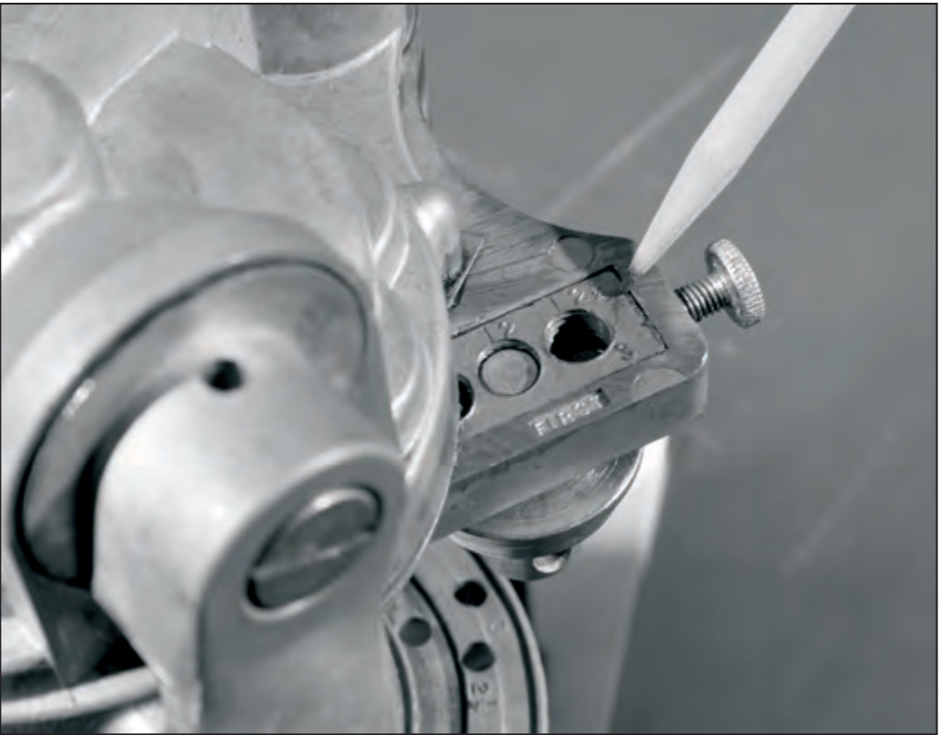
9. Move to Position “1”
Turn the crank clockwise until the “1” appears in the indicating window, as indicated by the pencil point in the photograph. The crank should again be hanging straight down.
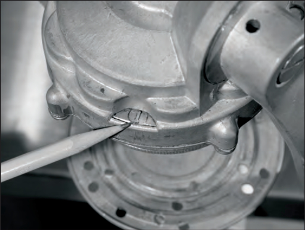
10. Snug the First Roller Screw
Finger tighten the first seaming roller screw. This removes slack yet allows the roller assembly to slide with rotation of the thumbscrew.
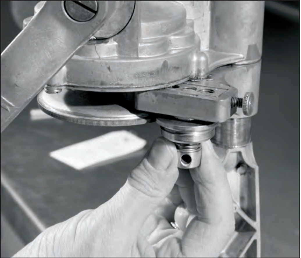
11. Gauge the First Roller
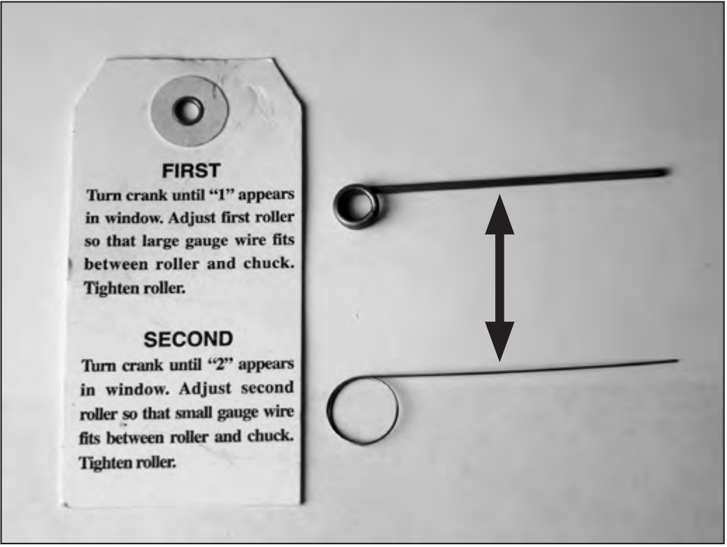
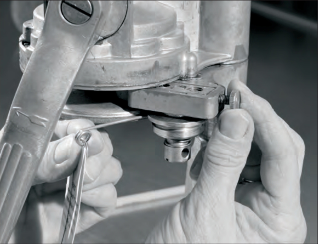
Make sure that the “1” appears in the indicating window. Insert the THICK/LARGE gauge wire between the chuck and the groove in the first seaming roller.
Tighten the thumbscrew while drawing (lightly pulling) the gauge wire until drag is felt. Leave the wire in place and tighten the thumbscrew an additional ¼ turn.
12. Set the First Roller
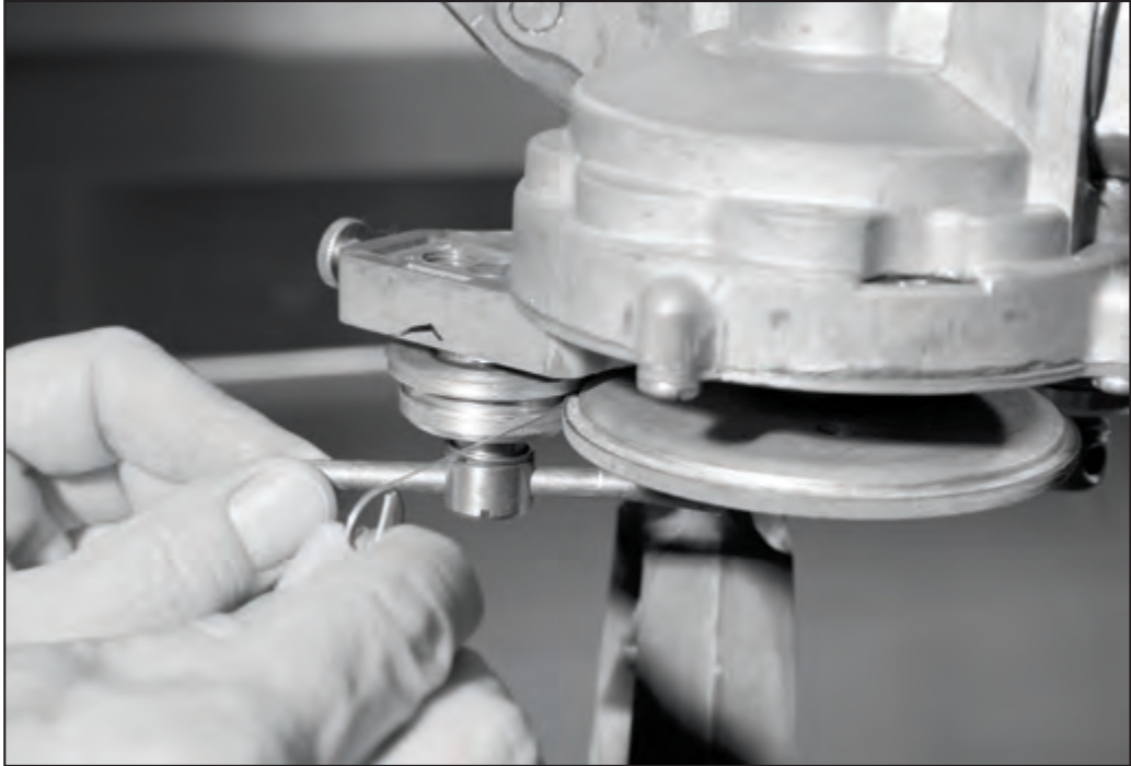
Lock the seaming roller screw in place by tightening with the 3-inch pin. Draw (lightly pull) again on the gauge wire — it must not move easily. If it moves, loosen the seaming roller screw slightly, and tighten the thumbscrew slightly. Repeat until the gauge wire cannot be moved easily.
Remove the gauge wire by turning the crank counterclockwise.
13. Adjusting the Second Seam Roller
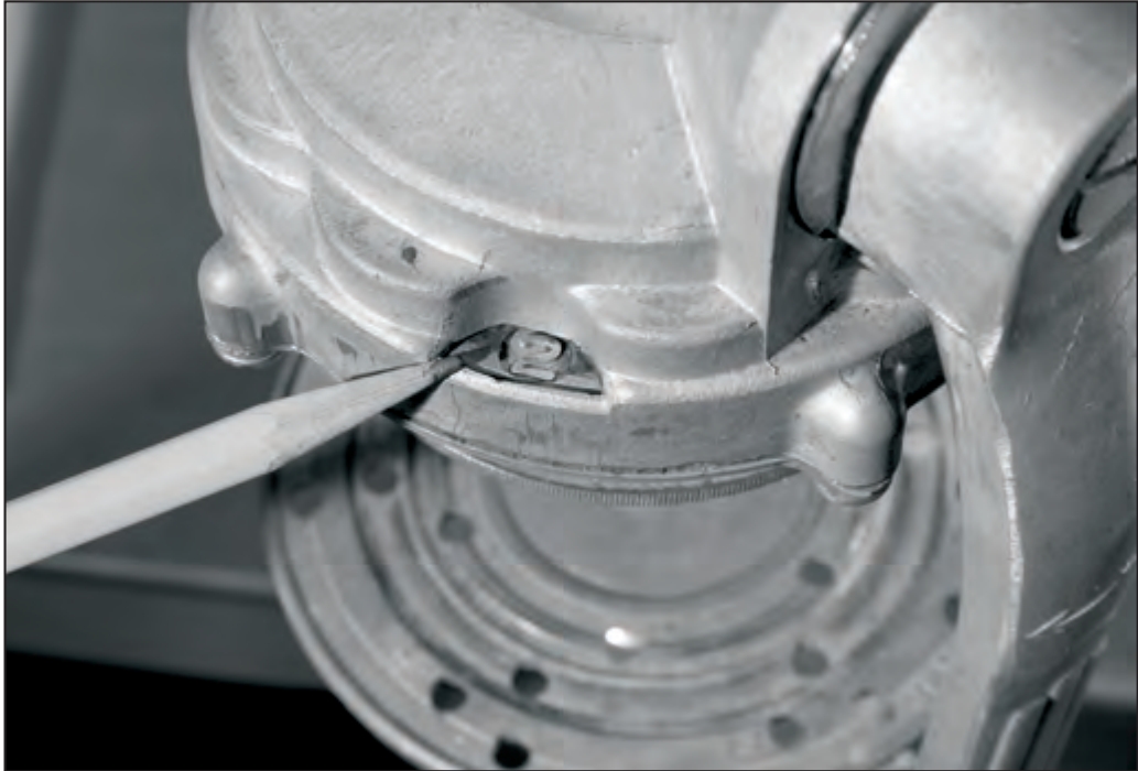
The second seaming roller is on the left. Turn the crank clockwise until the “2” appears in the indicating window. You will see a “C” pass before the “2” appears in the indicating window (pencil point in photograph).
14. Snug the Second Roller Screw
Move the seaming roller to the outside by sliding the 3-hole nut until it stops hard against the frame.
Finger tighten the second seaming roller screw. This removes the slack yet allows the roller assembly to slide with the rotation of the thumbscrew.
15. Gauge the Second Roller
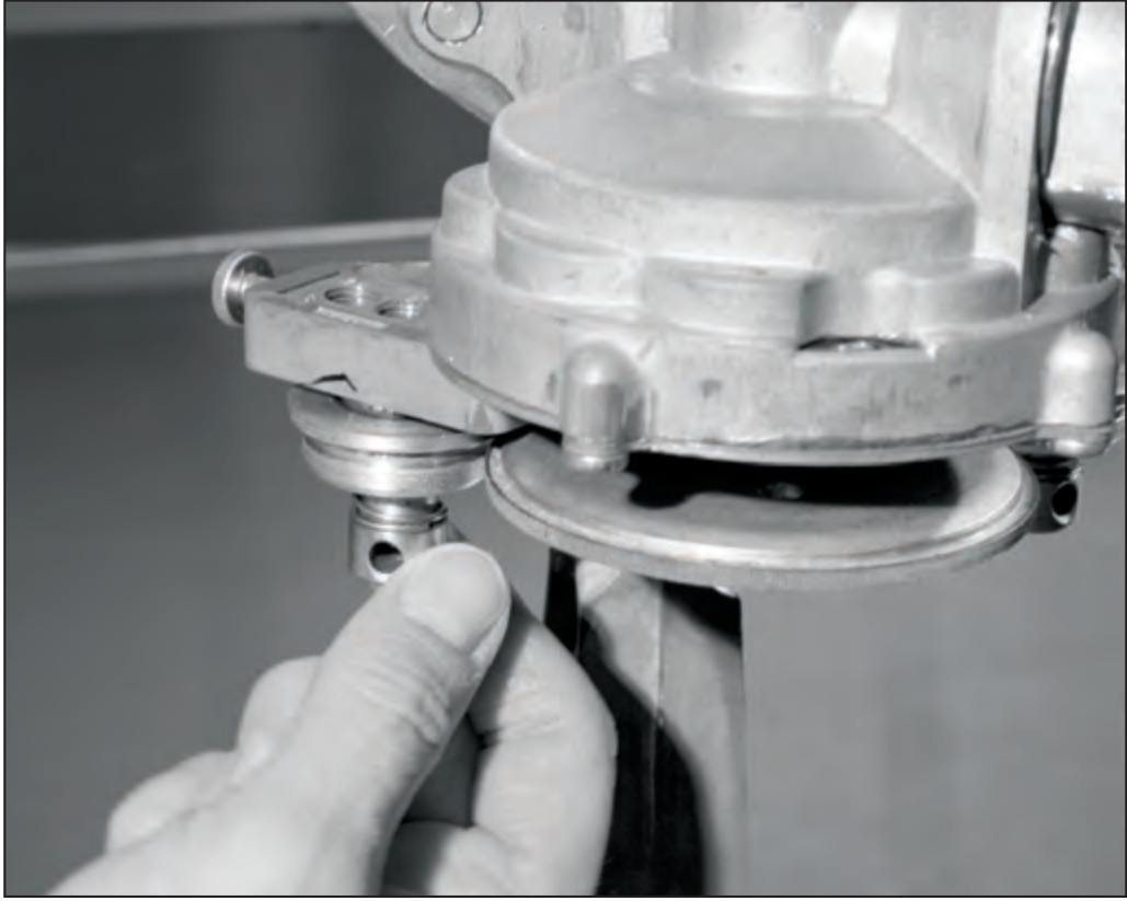
Make sure the “2” appears in the indicating window. Insert the THIN/SMALL gauge wire between the chuck and the groove in the second seaming roller.
Tighten the thumbscrew while drawing (lightly pulling) the gauge wire until drag is felt. Leave the wire in place and tighten the thumbscrew an additional ¼ turn.
16. Set the Second Roller
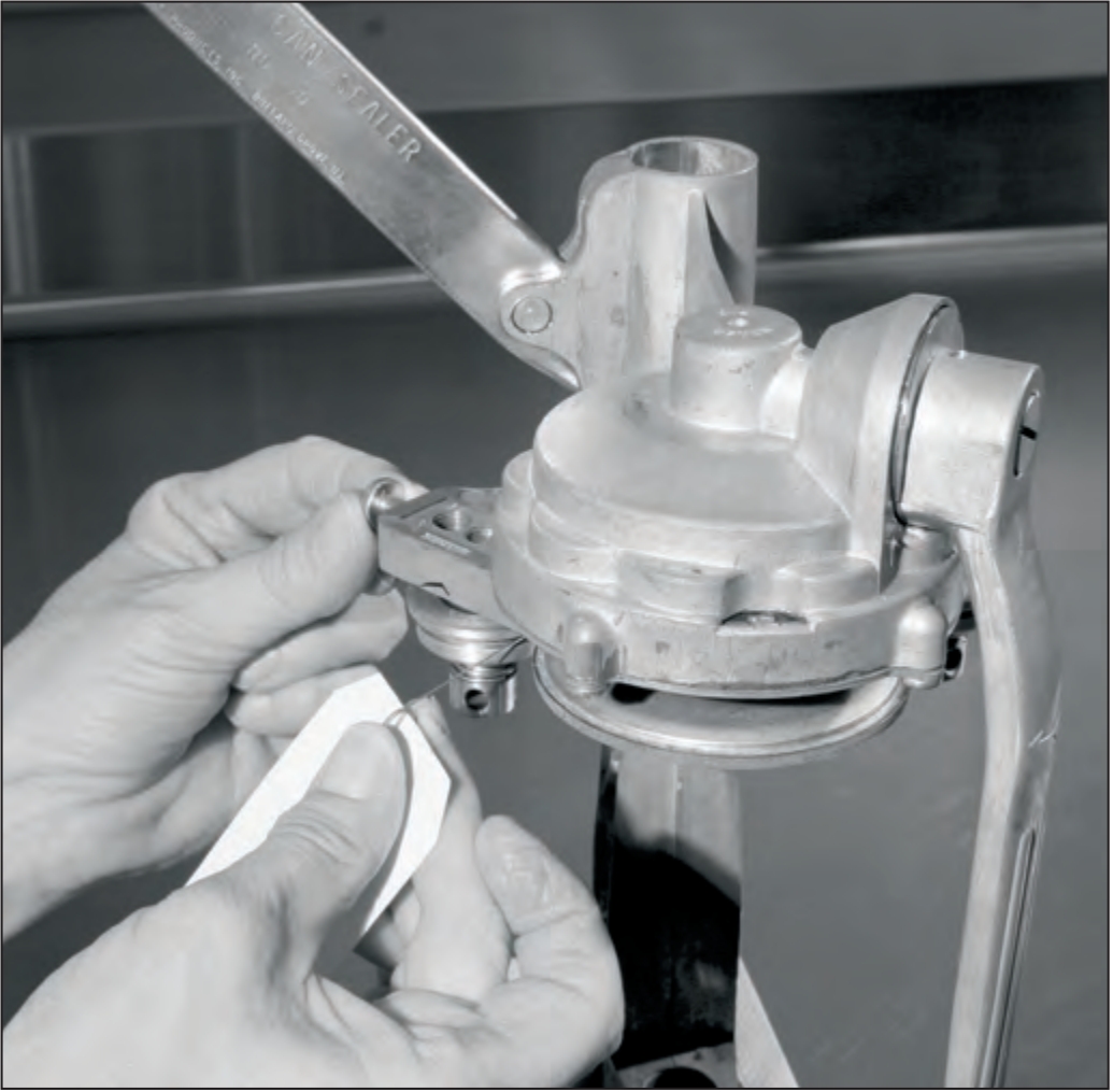
Lock the seaming roller screw in place by tightening with the 3-inch pin. Draw (lightly pull) again on the gauge wire — it must not move easily. If it moves, loosen the seaming roller screw slightly and tighten the thumbscrew slightly. Repeat until the gauge wire cannot be moved easily.
Remove the gauge wire by turning the crank counterclockwise.
17. Situate the Turntable
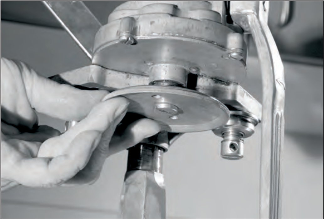
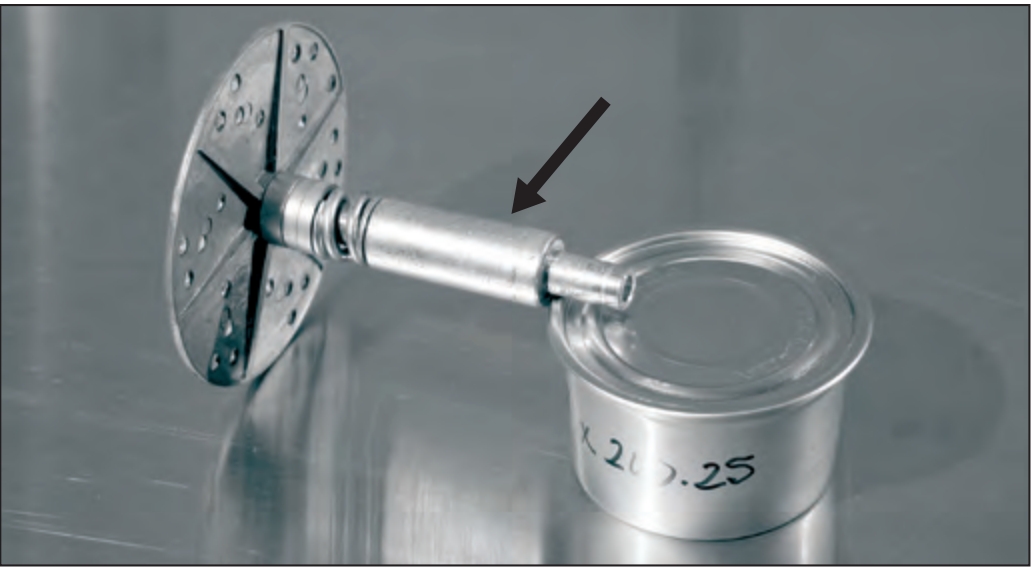
Select the required spacers and extension for your can size (see earlier entry above). Place the spacers, then the spring onto the shaft of the turntable. For the 307 x 200.25, ¼-pound flat salmon can, the turntable extension is required (arrow).
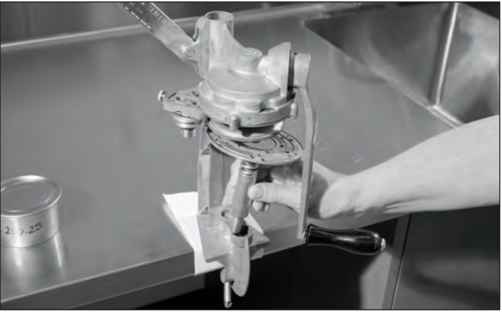
Situate the turntable by lifting the can sealer lever to the up position. Insert the turntable into the frame.
18. Make a Test Seam
Begin with the “0” in the indicating window and the crank hanging straight down. Raise the lever to the full up locked position. Center a can on the turntable, then center a lid (gasket down) on top of the can.
19. Lock Down the Can
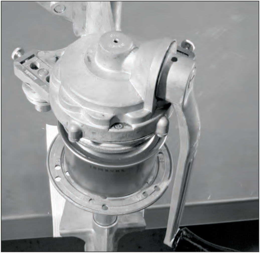
With the can and lid in the center of the turntable, slowly lower the lever, moving the can as necessary to keep it centered. Press the lever down to the locked position. This will, and should, require some force as you compress the turntable spring.
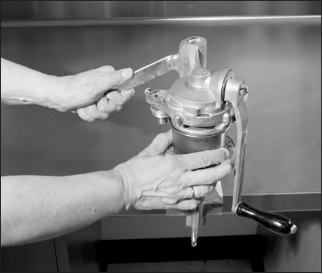
Form the Seam
Steadily rotate the crank clockwise through the entire cycle, starting and ending at “0” in the indicating window. The indicating window will display “0,” “1,” “C,” “2” — then back to “0” in a complete can seaming operation.
The crank should turn rather hard toward the end of each seaming operation as the seam is flattened against the can body.
Lift the lever and remove the sealed can.
Seal at least one empty sample can before filling and sealing cans for processing in a pressure canner. Evaluate the sample can seam for visual seam defects.
Visual Seam Defects
Visual seam defects are seen on the outside of the can seam. These defects include droop, vee, sharp seam, cut seam, incomplete seam and false seem. Each can should be inspected for visual seam defects before processing. Cans need to be free of all visual defects to be acceptable. If visual defects are present, the can seam is unacceptable.
An unacceptable or defective can seam could prevent the seam from being airtight, cause loss of the canned food through spoilage and be a health hazard if the bacteria that causes botulism enters the can through the defective seam.
Seams that do not pass the visual inspection for defects cannot be corrected by running them through the sealer a second time. The can sealer problem must be corrected. The contents of the can must be packed into a new can and the can reprocessed according to recommended instructions.
Remember! When defects are discovered, it is essential to determine the cause of the defects and to correct the problem.
See publication FNH-00023, "Visual Inspection of Can Seams in Home Food Preservation," for detailed information about causes and solutions for can seam defects.
Additional Cooperative Extension Publications
FNH-00023 Visual Inspection of Can Seams in Home Food Preservation
FNH-00125 Canning Fish in Cans
FNH-00129 Canning Smoked Fish in Cans
FNH-00222 Home Freezing of Fish
FNH-00223 Home Canning Smoked Fish and Home Smoking Fish for Canning
FNH-00227 Canning Meat in Cans
FNH-01282 Canning Meat and Fish in Cans - YouTube
Julie Cascio, Extension Faculty, Health, Home and Family Development. Originally produced by Brett Luick, Extension Foods and Nutrition Specialist, and Linda Tannehill.
Reviewed October 2024


