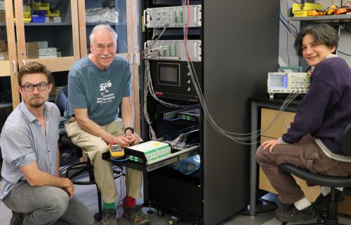
Microgrid prize winner tests in ACEP lab
October 15, 2019

In 2018, Intergrid received the grand prize laboratory testing award in the Alaska Center for Microgrid Technologies Commercialization competition. The company is developing an 80-kilowatt, three-phase 480 V SiC inverter capable of operating in an islanded microgrid either in parallel with other grid-forming sources or as the sole grid-forming source.
Intergrid, an inverter company based in Temple, New Hampshire, specializes in power electronics for renewable energy. Intergrid has designed inverters ranging in power from 200 watts to 200 kW, including the inverter for the Skystream wind turbine, which has 10,000 units in the field.
As part of the award, Intergrid spent two weeks in Fairbanks in the ACEP Engineering Learning and Innovation Facility lab, where ACEP engineers have been providing support in the following areas: development and validation of three-phase inverter control algorithms using controller hardware-in-the-loop (CHIL), validation of the integrated microgrid control approach using the same CHIL platform including easYgen genset controllers, and programming support for the programmable logic controller-based microgrid controller, which will include various dispatch strategies.
ACEP’s Opal-RT-based CHIL platform has proved invaluable for this work. A typical remote microgrid with renewables might include diesel generators; renewable sources such as wind, solar or hydro coupled to the grid with an inverter; distribution lines; and various loads. Developing an overall microgrid control strategy as well as individual component controllers (especially the inverter) is most often done via pure simulation, where both the power system components and the control algorithms are simulated. However, there will still be significant testing required when the controls are implemented on the real-world platform. In addition to troubleshooting the actual hardware implementation, including wire connections and the input/output circuitry, or IO, there will also be considerable time required to validate the controls as coded on the real-world control chip. In a CHIL experiment, all the power system components mentioned above are modeled on a real-time simulator. The RTS is capable of simulating the voltages and currents of these components in real-time. What does this mean? It means that if an event would take one second in the real world, it will take the RTS one second to simulate the same thing. Why is this valuable? Because if you also have sufficient IO interfaces to digital signals from the model to real-world signals for the controller, and vice versa, you can use your ready-to-go real-world controller to control these models just as if it were controlling the real thing.
For more information email Amanda Byrd at agbyrd@alaska.edu.


